
USB
Chip Name and Kernel Version
- Chip Name: RK3576
- Kernel Version: Linux-6.1
Preface
This guide provides the development guide for the RK3576 USB module, aiming to help developers understand the hardware circuit design and software DTS configuration of the RK3576 USB controller and PHY. This allows for flexible design and rapid development based on the USB application requirements of the product. This guide is intended for technical support engineers, software development engineers, and hardware development engineers.
1. Introduction to RK3576 USB Controller and PHY
RK3576 supports 2 independent USB 3.1 OTG controllers, 2 independent USB 2.0 PHYs, 1 USB 3.1/DP Combo PHY, and 1 USB 3.1/SATA/PCIe Combo PHY. For detailed features, please refer to the RK3576 TRM.
New features of RK3576 USB:
- OTG0/1 supports MMU, allowing the USB controller hardware to access memory space beyond 4GB.
- OTG1 supports CCI to ensure cache consistency, while OTG0 does not.
- OTG0 DP/DM supports multiplexing with UART/JTAG, enabled by default, and requires the RK USB to DEBUG adapter board.
Note:
- The physical layer transmission rate of USB 3.1 Gen1 is 5Gbps, and the physical layer transmission rate of USB 2.0 is 480Mbps.
- The USB 3.1/DP Combo PHY supports 4 x lanes and can simultaneously support USB 3.1 + DP 2 x lanes.
- The USB 3.1/SATA/PCIe Combo PHY can only support one working mode at a time; USB 3.1 and SATA/PCIe interfaces are mutually exclusive.
Table 1: Connection relationship of RK3576 USB controller and PHY
| USB Interface Name (Schematic) | USB Controller | USB PHY |
|---|---|---|
| USB OTG0 | OTG0 (DWC3 & xHCI) | USB3.1/DP Combo PHY + USB2.0 PHY0 |
| USB OTG1 | OTG1 (DWC3 & xHCI) | USB3.1/SATA/PCIe Combo PHY1 + USB2.0 PHY1 |
The pin correspondence between the RK3576 USB controller and chip-side USB data transmission is shown in Table 2 below.
Table 2: Correspondence between RK3576 USB controller and USB pins
| USB Controller/Pin | RK3576 USB Data Pins |
|---|---|
| USB 3.1 OTG0 | USB2_OTG0_DP/USB2_OTG0_DM, USB3_OTG0_SSRX1P/USB3_OTG0_SSRX1N, USB3_OTG0_SSTX1P/USB3_OTG0_SSTX1N, USB3_OTG0_SSRX2P/USB3_OTG0_SSRX2N, USB3_OTG0_SSTX2P/USB3_OTG0_SSTX2N |
| USB 3.1 OTG1 | USB2_OTG1_DP/USB2_OTG1_DM, USB3_OTG1_SSTXP/USB3_OTG1_SSTXN, USB3_OTG1_SSRXP/USB3_OTG1_SSRXN |
The internal connection relationship between the RK3576 USB controller and PHY, as well as the corresponding common USB physical interfaces, is shown in Figure 1 below. Figure 1: Schematic diagram of the connection between RK3576 USB controller and PHY
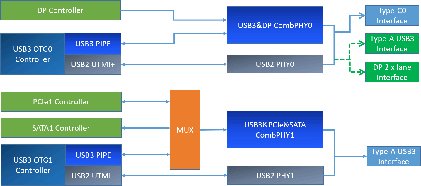
Note:
- The USB interface types supported by RK3576 are not limited to the Type-C/A USB interface types described in Figure 1. It can also support all common USB interfaces, including Type-C USB 2.0/3.1, Type-A USB 2.0/3.1, Micro USB 2.0/3.1, etc. To adapt to different USB circuit designs and interface types, the Linux-6.1 kernel USB driver has been made software-compatible. Developers only need to correctly configure the Linux USB DTS according to the USB hardware circuit of the product to enable the corresponding USB interface functions. For detailed USB DTS configuration methods, please refer to the RK3576 USB DTS configuration.
- Special usage restrictions: The OTG1/PCIe1/SATA1 controller bus access is mutually exclusive. If PCIe1 or SATA1 is used in the hardware circuit design, the OTG1 USB2 and USB3 functions cannot be used.
2. RK3576 USB Config Map
The 2 independent USB controllers of RK3576 can support the configuration methods listed in Figures 2 to 4, forming different product forms. USB OTG0 can support 5 types of hardware circuit designs: Config0: Type-C0 USB3.1 OTG0 with DP function Config1: USB 2.0 OTG0 + DP 4 x Lane (Swap off) Config2: USB 2.0 OTG0 + DP 4 x Lane (Swap on) Config3: USB 3.1 OTG0 + DP 2 x Lane (Swap on) Config4: USB 3.1 OTG0 + DP 2 x Lane (Swap off) USB OTG1 supports 2 types of hardware circuit designs: Config0: USB 2.0 only OTG1 Config1: USB 3.1 OTG1 For a more detailed USB configuration table, please refer to the RK3576 SDK EVB reference schematic section USB/DP Configure Map. Note:
- USB 2.0/3.1 OTG1 cannot be used simultaneously with PCIe1/SATA1.
- The lane correspondence for USBDP Swap on/off configurations is as follows: Swap off:Lane0/1/2/3 TxData mapping to Lane0/1/2/3_TXDP/N Swap on: Lane0/1/2/3 TxData mapping to Lane2/3/0/1_TXDP/N
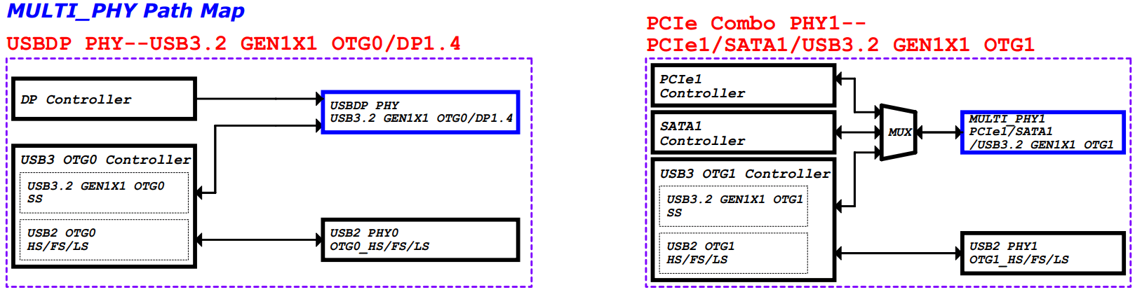 Figure 2: RK3576 USB Path Map
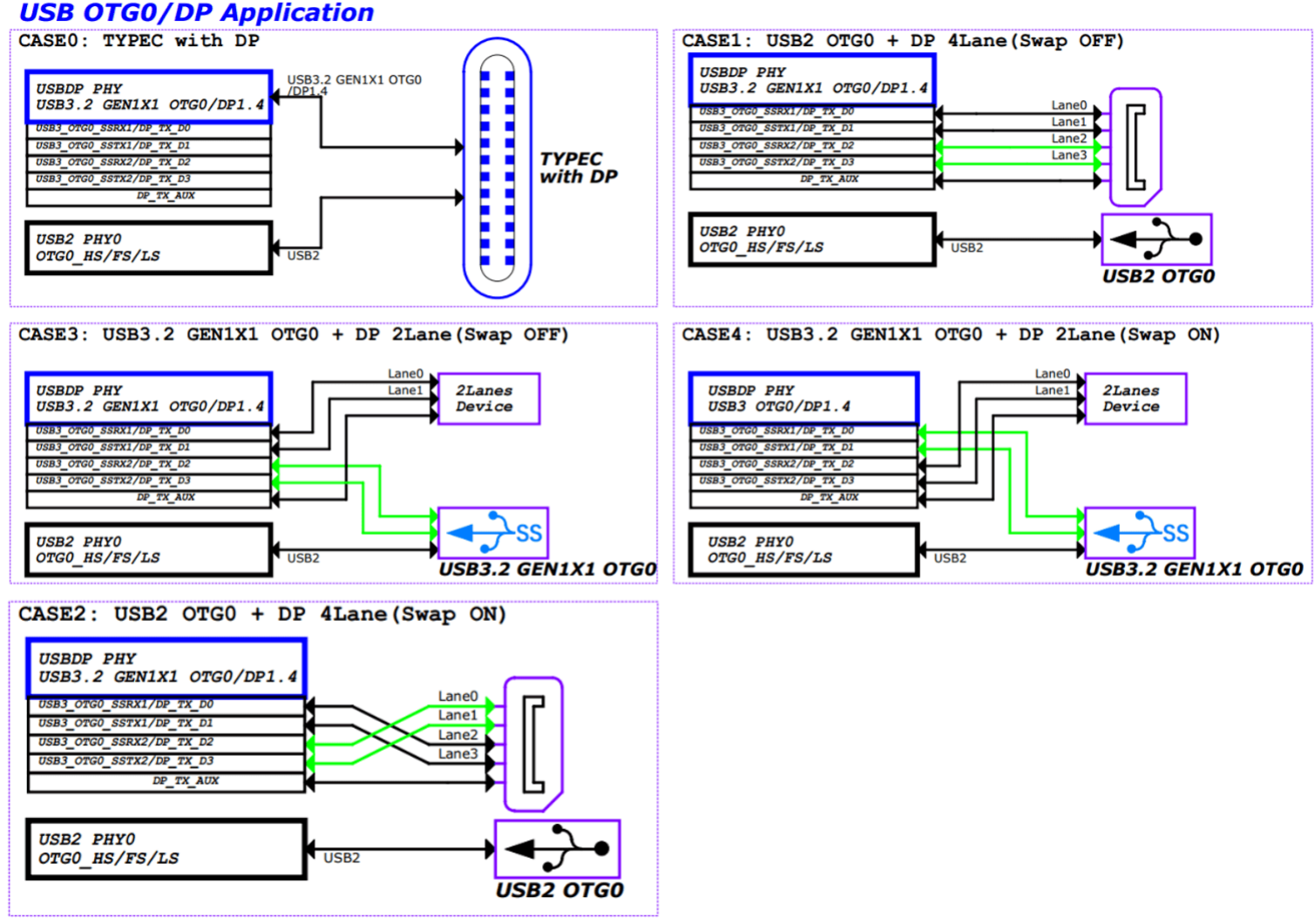
Figure 3: RK3576 OTG0 USBDP Path Map
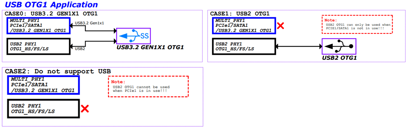 Figure 4: RK3576 OTG1 MULTI PHY Path Map
3. RK3576 USB Hardware Circuit Design
This chapter mainly describes the various hardware circuit design solutions supported by RK3576 USB in practical applications. RK3576 can support the following interfaces:
- USB30/DP1.4 MULTI0
- USB30/PCIE2.0/SATA30 MULTI1
3.1 USB Controller Power Supply and Power Management
The power supply for the RK3576 USB controller is VD_LOGIC. At the same time, the chip internally designs a power domain specifically for the USB controller: USB3.1 OTG0 is located in PD_USB; USB3.1 OTG1 is located in PD_PHP.
In actual usage scenarios, the Linux USB controller driver will dynamically switch the PD of the USB controller on and off based on the working status of the USB interface, using the Linux PM Runtime mechanism to reduce the power consumption of the USB controller. When the system enters deep sleep, in order to achieve optimal power consumption, the software will forcibly turn off all PDs of the USB controller. Therefore, in the actual application scenarios of the product, if it is necessary to maintain the working status of the USB controller registers during deep sleep, it is necessary to call the device_init_wakeup function in the USB controller driver to avoid turning off the PD of the USB controller during deep sleep.
The power consumption control strategy for the USB controller is as follows:
- For unused USB controllers, the corresponding controller DTS node needs to be configured as disabled;
- For USB controllers that are already enabled in the kernel, the kernel USB driver already supports the USB controller Auto suspend function (when no external device is connected to the USB HOST interface, the controller automatically enters suspend low power mode). Therefore, developers do not need to debug the dynamic power management of the USB controller.
3.2 USB PHY Power Supply and Power Management
3.2.1 USB 2.0 PHY Power Supply and Power Management
RK3576 supports 2 independent USB 2.0 PHYs. Internally, all USB 2.0 PHYs belong to VD_USBPHY, and they all share the 3 external power supplies shown in Figure 5.
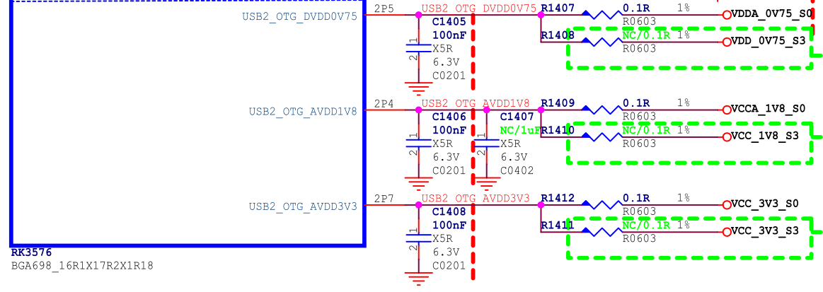
It should be noted that in the actual circuit, if the supply voltage of the USB 2.0 PHY exceeds the specified maximum value or is lower than the specified minimum value, it may cause abnormal USB connection.
Table 3: USB 2.0 PHY Power Supply Voltage Requirements
| Power Supply | Minimum | Normal | Maximum | Unit |
|---|---|---|---|---|
| USB2_OTG_DVDD_0V75 | 0.6975 | 0.75 | 0.825 | V |
| USB2_OTG_AVDD_1V8 | 1.674 | 1.8 | 1.98 | V |
| USB2_OTG_AVDD_3V3 | 3.069 | 3.3 | 3.63 | V |
The power consumption control strategy for USB 2.0 PHY is as follows:
- In order to support the Maskrom USB firmware download function, it is necessary to ensure that the three power supplies of USB 2.0 PHY are normal;
- After the system is powered on, all USB 2.0 PHYs are in Normal mode by default. The software configures USB PHY1/PHY2/PHY3 to be in the lowest power consumption IDDQ mode (already supported by SDK) during the U-Boot SPL stage. After entering the system, the kernel USB driver will set the corresponding USB 2.0 PHY to exit IDDQ mode according to the application requirements;
- For USB 2.0 PHYs that are already enabled in the kernel, the kernel USB 2.0 PHY driver will automatically perform dynamic power consumption control on the PHY. When a device is detected to be inserted, it will automatically set the USB 2.0 PHY to Normal mode. When no device is detected to be inserted, it will automatically set the USB 2.0 PHY to Suspend mode.
The power consumption data of USB 2.0 PHY in different working modes is shown in Table 4 below
Table 4: USB 2.0 PHY Power Consumption Data (Statistics for a single USB 2.0 PHY)
| Power Supply | Read/Write Data | Dynamic Sleep | PHY Disabled | Deep Sleep | Unit |
|---|---|---|---|---|---|
| USB20_DVDD_0V75 | 8.9mA | 2.8mA | 0.05mA | 0mA | mA |
| USB20_AVDD_1V8 | 8.6mA | 3.34mA | 0.05mA | 0mA | mA |
| USB20_AVDD_3V3 | 2.5mA | 0.14mA | 0.05mA | 0mA | mA |
Note:
- Power consumption during read/write data testing: Connect U2 disk to copy data, PHY is in Normal mode;
- Power consumption during dynamic sleep testing: USB 2.0 PHY's DTS is enabled, but no USB peripheral is connected, PHY is in Suspend mode;
- Power consumption during PHY disabled testing: USB 2.0 PHY's DTS is disabled, PHY is in IDDQ mode;
- Power consumption during deep sleep testing: All three power supplies of USB 2.0 PHY are turned off;
3.2.2 USB 3.1 PHY Power Supply and Power Management
RK3576 supports two types of USB 3.1 Combo PHY:
- USB 3.1/DP Combo PHY
- USB 3.1/PCIe/SATA Combo PHY The power supply and power consumption control methods for these two types of USB 3.1 Combo PHY are different and will be explained separately below.
3.2.2.1 USB 3.1/DP Combo PHY
RK3576 USB3.1 OTG0 uses USB 3.1/DP Combo PHY. Internally, the USB 3.1/DP Combo PHY of RK3576 belongs to VD_USBDPPHY (Alive). There are two independent power supplies externally, as shown in Figure 6.
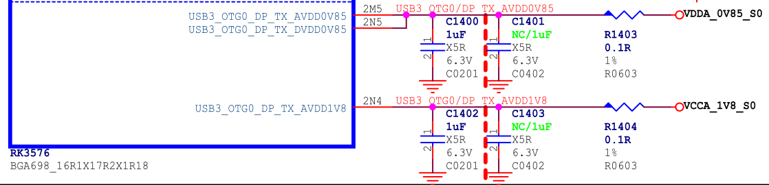
Figure 6: Power Supply of RK3576 USBDP Combo PHY
Table 5: USB 3.1/DP Combo PHY Power Supply Voltage Requirements
| Power Supply | Minimum | Normal | Maximum | Unit |
|---|---|---|---|---|
| VDD_0V85/VDDA_0V85 | 0.8075 | 0.85 | 0.8925 | V |
| VDDH_1V8 | 1.71 | 1.8 | 1.89 | V |
The power consumption control strategy for USB 3.1/DP Combo PHY is as follows:
- After the system is powered on, when the USBDP PHY is in an uninitialized state, the power consumption is the lowest;
- In application scenarios that support USBDP, the kernel USBDP PHY driver will automatically perform dynamic power consumption control on the PHY. When a device is detected to be inserted, it will automatically set the USBDP PHY to P0 State. When no device is detected to be inserted, it will automatically set the USBDP PHY to P3 State (applied to Type-A interface) or reset state (applied to Type-C interface);
- For application scenarios where USBDP is not used (i.e., neither USB3.1 nor DP is used), the power supply of the USBDP PHY can be designed to be either normally powered or externally powered off, depending on the project requirements. The specific instructions are as follows: (1) If the USB3.1 firmware download function is to be supported, the power supply of the USBDP PHY must be normally powered; (2) If the USB3.1 firmware download function is not required, it is recommended to externally power off the power supply of the USBDP PHY. However, the DTS configuration needs to be modified. Please refer to the USB PHY power-off DTS configuration for details. (3) If the USB3.1 firmware download function is not required, and the power supply of the USBDP PHY is normally powered, it is recommended to configure the USBDP PHY DTS node as disabled, keeping the PHY in the powered-on but uninitialized state, which consumes the least power;
Table 6: USB 3.1/DP Combo PHY Power Consumption Data
| Power Supply | Read/Write Data | Dynamic Sleep | PHY Disabled | Deep Sleep | Unit |
|---|---|---|---|---|---|
| VDD_0V85/VDDA_0V85 | 101.6mA | 5mA | 2mA | 0mA | mA |
| VDDH_1V8 | 29mA | 0mA | 0mA | 0mA | mA |
| Note: |
- Power consumption during read/write data testing: Connect U3 disk to copy data, PHY is in P0 state;
- Power consumption during dynamic sleep testing: Type-C interface, no USB peripheral connected, PHY is in reset state;
- Power consumption during PHY disabled testing: PHY's DTS node is configured as disabled, PHY is in uninitialized state, in this state, the power consumption is the lowest;
- Power consumption during deep sleep testing: Both power supplies of the PHY are turned off;
The method to disable the USBDP PHY in the kernel is as follows:
&usbdp_phy {
        status = "disabled";
};
&usbdp_phy_dp {
        status = "disabled";
};
&usbdp_phy_u3 {
        status = "disabled";
};
3.2.2.2 USB 3.1/PCIe/SATA Combo PHY
RK3576 USB3.1 OTG1 uses USB3.1/PCIe/SATA Combo PHY1. Internally, this PHY belongs to PD_BUS (Alive), and there are two independent power supplies externally, as shown in Figure 7.
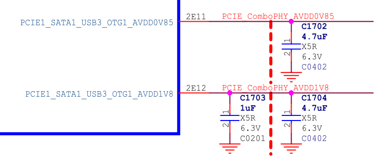 Figure 7: Power Supply of RK3576 USB 3.1/PCIe/SATA Combo PHY
Table 7: USB 3.1/PCIe/SATA Combo PHY Power Supply Voltage Requirements
| Power Supply | Minimum | Normal | Maximum | Unit |
|---|---|---|---|---|
| AVDD_0V85 | 0.8 | 0.85 | 0.935 | V |
| AVDD_1V8 | 1.62 | 1.8 | 1.98 | V |
The power consumption control strategy for USB 3.1/PCIe/SATA Combo PHY is as follows:
- When the chip is powered on, the USB 3.1/PCIe/SATA Combo PHY is set to work by default. The software sets the PHY to reset state during the U-Boot SPL stage to keep the PHY at the lowest power consumption. After entering the kernel, the USB controller driver will release the PHY from reset by calling the rockchip_combphy_init() function.
- Dynamic power consumption control of the PHY: When the Combo PHY works in USB mode, the PIPE state (P0/P1/P2/P3) of the PHY is automatically controlled by the USB controller hardware, dynamically entering and exiting P0/P1/P2/P3 states according to different working scenarios. For example, when no USB device is inserted, the PIPE is in P3 state; when a U3 disk is inserted, it switches to P0 state; when connecting to a U3 HUB, as long as the downstream port of the HUB is not connected to other USB peripherals, the PIPE state will automatically enter P3 state low power consumption. When a USB peripheral is inserted into the U3 HUB, the PIPE state switches to P0 automatically. (Note: P0 is the normal working state, P3 is the lowest power consumption state)
- When the USB 3.1 OTG1/PCIe/SATA interface is clearly not in use, the corresponding Combo PHY can be powered off, but the DTS configuration needs to be modified. Please refer to the USB PHY power-off DTS configuration for details.
- When the PHY is powered, if this PHY is not used, the corresponding PHY DTS node needs to be configured as disabled, keeping the PHY in reset state, which consumes the least power;
Table 8: USB 3.1/SATA/PCIe Combo PHY Power Consumption Data
| Power Supply | Read/Write Data | Dynamic Sleep | PHY Disabled | Deep Sleep | Unit |
|---|---|---|---|---|---|
| AVDD_0V85 | 44.5mA | 9.6mA | 0.4mA | 0mA | mA |
| AVDD_1V8 | 5.2mA | 0.5mA | 0.2mA | 0mA | mA |
| Note: |
- Power consumption during read/write data testing: Connect U3 disk to copy data, PHY is in P0 state;
- Power consumption during dynamic sleep testing: PHY DTS is enabled, but no USB peripheral is connected, PHY is in P3 State;
- Power consumption during PHY disabled testing: PHY's DTS node is configured as disabled, PHY is in reset state;
- Power consumption during deep sleep testing: Both power supplies of the PHY are turned off. The method to disable the USB 3.1/PCIe/SATA Combo PHY in the kernel is as follows:
&combphy1_psu {
        status = "disabled";
};
3.3 USB Hardware Circuit Design
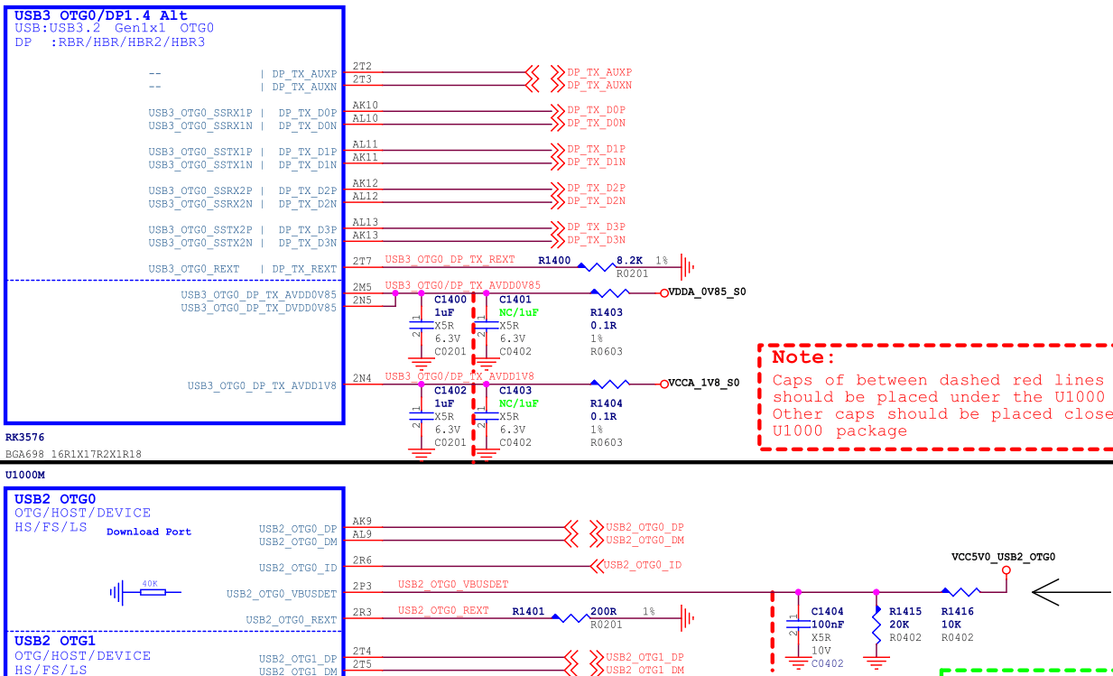
3.3.1 USB2_OTG0_VBUSDET Circuit Design
USB2_OTG0_VBUSDET is used for detecting the connection and disconnection of the device when USB is used as a Device. The design considerations are as follows:
- Designed to support PD-enabled Type-C interfaces, i.e., supporting external Type-C controller chips (such as FUSB302 or HUSB311), refer to the circuit design of RK3576 EVB1 Type-C (USB2_OTG0_VBUSDET is fixedly pulled up to VCC_3V3_S0). The software driver can detect the connection and disconnection of the USB Device through the CC of the Type-C controller chip;
- For other circuit design solutions that do not support external Type-C controller chips (such as Type-C USB 2.0 only, Type-A USB 3.1, Micro USB 2.0/3.1), USB2_OTG0_VBUSDET should still be designed according to the traditional voltage divider circuit, connected to the VBUS pin of the USB interface, and VBUSDET should not be designed for constant power supply (if there is a need for USB HOST, independent GPIO or PMIC VBUS control is required, and should not be reused with other USB HOST VBUS control circuits);
- The high-level range of the chip input USB2_OTG0_VBUSDET should be in
[0.9V ~ 3.3V];
3.3.2 Maskrom USB Circuit Design
Maskrom supports USB3.1 firmware download, and is backward compatible with USB2.0 firmware download. The hardware design requirements are as follows:
- The power supplies related to USB 2.0 PHY must be powered, please refer to USB 2.0 PHY power supply and power management for details;
- The power supplies related to USBDP PHY can be designed to be normally powered or powered off externally, depending on the actual project requirements. Please refer to USB 3.1 PHY power supply and power management for details; If USB3.1 firmware download function is to be supported, the power supplies related to USBDP PHY must be powered, and USB3_OTG0_TX1/RX1 should be connected to the USB download port.
- Maskrom USB enumeration does not rely on the voltage level of USB2_OTG0_VBUSDET;
- Burning tool configuration instructions (1) The USB 3.1 firmware download function must be used with Windows tool v3.28 or Linux tool v2.30 or updated versions, and manually modify the config.ini of the burning tool. Windows tool config.ini modification: USB3_TRANSFER=TRUE Linux tool config.ini modification: usb3_transfer_on=true
(2) In hardware circuit design, if only OTG0 USB2 only is supported and USBDP PHY is not powered (i.e., USB3_OTG0_DP_TX_AVDD0V85, USB3_OTG0_DP_TX_DVDD0V85, USB3_OTG0_DP_TX_AVDD1V8 are not powered), the USB3 function of the burning tool needs to be turned off, otherwise, it will lead to Maskrom firmware download failure.
3.3.3 USB2 Support for Waking Up the System Circuit Design
USB2 supports waking up the system through DP/DM, and this function has special requirements for power supply during deep sleep, as follows:
- The three external power supplies of USB2 PHY (USB2_OTG_DVDD_0V75, USB2_OTG_AVDD_1V8, USB2_OTG_AVDD_3V3) must be powered;
- The VBUS of the USB interface should provide power to the USB peripheral;
- The external power supply of RK3576's OSC (OSC_AVDD1V8) should be powered;
- The external power supply of RK3576's PMU should be powered;
- The external power supply of RK3576's Logic can be powered or turned off. It is recommended to turn off Logic to reduce the deep sleep power consumption.
3.3.4 Type-C USB 3.1/DP Full-Function Hardware Circuit
Taking the RK3576 EVB1 USB 3.1 OTG0 Type-C hardware circuit design as an example.
- The Type-C circuit must be used with an external Type-C controller chip to achieve the complete function of Type-C (including: detection of front and back, PD charging negotiation, Alternate Mode negotiation). RK3576 can support most of the commonly used Type-C controller chips, please refer to the Type-C controller chip support list for details;
- In order to support high-voltage charging function and reduce the risk of hardware circuit, USB2_OTG0_VBUSDET should not be connected to the VBUS of the Type-C interface, but should be fixedly pulled up to 3.3V (as shown in Figures 8 and 9, USB2_OTG0_VBUSDET is connected to VCC_3V3_S0), but it cannot be left floating;
- USB2_OTG0_ID is only used for the OTG function of Micro interface type, and is not required for Type-C circuit, so it can be left floating.
- TYPEC_SBU1/TYPEC0_SBU2 is only used for AUX communication of DP Alternate Mode. According to the AUX protocol requirements, the SBU1/SBU2 needs to be pulled up to the corresponding level according to the front and back insertion of Type-C. Since the automatic pull-up of SBU1/SBU2 is not implemented inside the RK3576 chip, the external circuit needs to add two GPIO controls (corresponding to TYPEC_SBU1/TYPEC_SBU2 in Figure 9). There is no requirement for the default pull-up and pull-down of GPIO, and any GPIO can be selected. In software, the properties sbu1-dc-gpios and sbu2-dc-gpios of the usbdp_phy node need to be modified for adaptation;
- For the software configuration of Type-C USB DTS, please refer to the Type-C USB 3.1/DP Full-Function DTS Configuration;
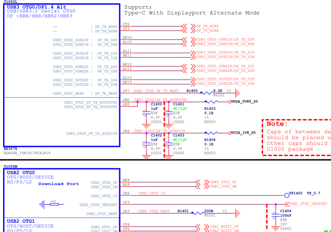 Figure 8: RK3576 Type-C Circuit
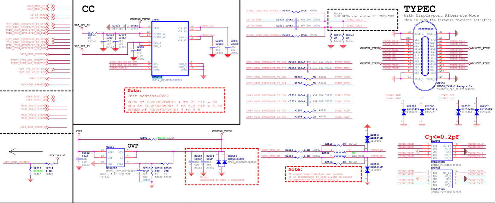 Figure 9: RK3576 Type-C Interface
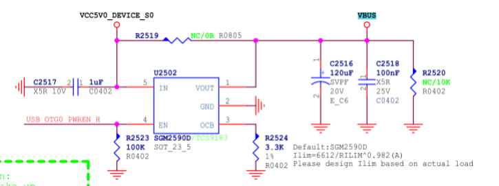 Figure 10: RK3576 Type-C VBUS Control Circuit
3.3.5 Type-C to Type-A USB 3.1/DP Hardware Circuit
This scheme is suitable for RK3576 USB 3.1 OTG0 Type-C can be split into independent Type-A USB 3.1 interface and DP (2 x Lane) interface. Taking the RK3576 EVB2 Type-C to Type-A USB 3.1/DP hardware circuit design as an example.
- Type-A USB 3.1 uses USB3_OTG0_SSRX1P/N and USB3_OTG0_SSTX1P/N (corresponding to chip internal USBDP PHY's lane0/1), while DP uses DP_TX_D2P/N and DP_TX_D3P/N (corresponding to chip internal USBDP PHY's lane2/3);
- If the USB OTG has applications for Device/HOST, it is recommended that USB2_OTG0_VBUSDET be connected to the VBUS of the Type-A USB interface through a 30KΩ resistor in series;
- The power supply (VCC5V0_USB30_HOST0) of Type-A VBUS is controlled by GPIO. When OTG is in Device mode, the VBUS output is turned off. When OTG is in HOST mode, the VBUS output is turned on. In addition, the output current of the voltage regulator chip SGM2590D is determined by the resistor connected to the OCB pin, with a maximum current
Ilim(A)=6612/RILIM^0.982, as shown in Figure 12, the VBUS output current is limited to 2.3A; - For the DTS configuration corresponding to Type-C to Type-A USB 3.1/DP, please refer to the Type-C to Type-A USB 3.1/DP DTS Configuration; Note: In theory, the hardware circuit can also be designed as Type-A USB 3.1 using lane2/3, DP using lane0/1, but the software needs to modify the property rockchip,dp-lane-mux of the usbdp_phy node to adapt to the hardware design.
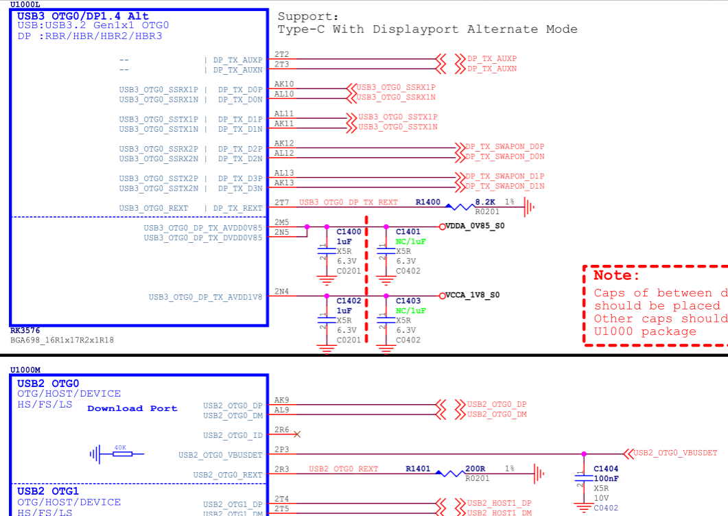
Figure 11: RK3576 Type-A USB 3.1/DP Circuit
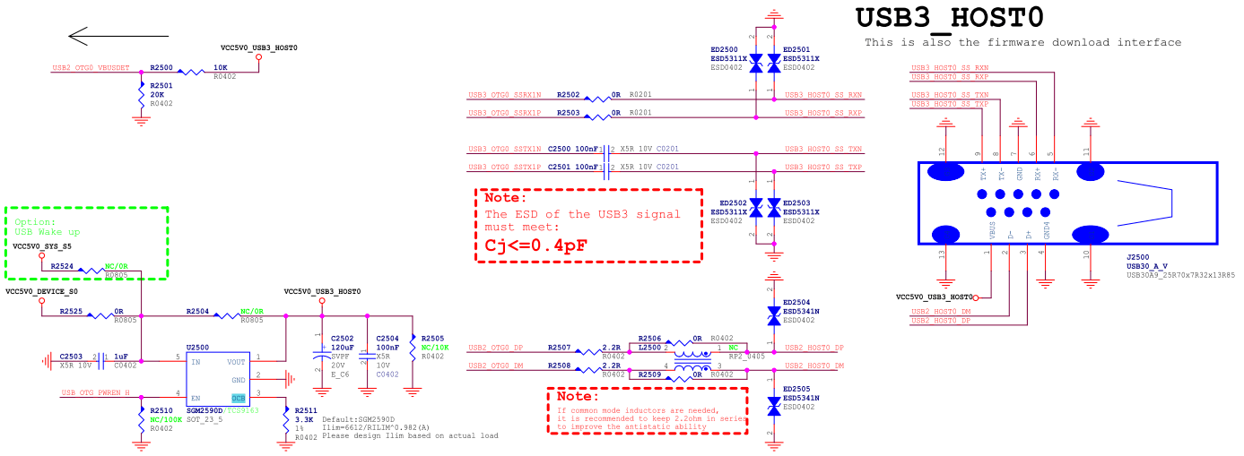
Figure 12: RK3576 Type-A USB3.1 Interface
3.3.6 Type-C to Type-A/Micro USB 2.0/DP Hardware Circuit
This scheme is suitable for RK3576 USB 3.1 OTG0 Type-C can be split into independent Type-A USB 2.0 interface and DP (4 x Lane) interface. Taking the RK3576 TEST2 Board Type-C to Type-A USB 2.0/DP hardware circuit design as an example.
- TYPEC USBDP PHY's 4 x Lane is fully used for DP interface, USB is not used for USBDP PHY.
- TYPEC USB is only used for HOST mode. USB2_OTG0_ID and USB2_OTG0_VBUSDET can be left floating.
- The power supply (VCC5V0_USB2_OTG0) of Type-A VBUS is controlled by GPIO. When OTG is in HOST mode, the VBUS output is turned on. In addition, the voltage regulator chip SGM2590D also has current limiting configuration.
- For the DTS configuration corresponding to Type-C to Type-A USB 2.0/DP, please refer to the Type-C to Type-A/Micro USB 2.0/DP DTS Configuration.
[Image Placeholder]
Figure 13: RK3576 Type-A USB 2.0/DP Circuit
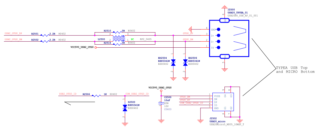
Figure 14: RK3576 Type-A/Micro USB2 Interface
3.3.7 Type-A USB3.1 OTG1 Hardware Circuit
As mentioned earlier, the key difference between RK3576 USB3.1 OTG0 and OTG1 is the connection of the USB3 PHY. Therefore, the R3576 USB 3.1 OTG1 non-Type-C hardware circuit is basically the same as the USB 3.1 OTG0 USB circuit. For the full-function Type-C circuit, an additional USB3.1 Switch chip (such as FUSB340) and a Type-C controller (such as FUSB302) need to be added between OTG1 and the Type-C interface.
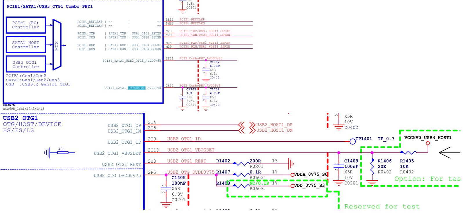
Figure 15: RK3576 USB3.1 OTG1 Interface
4. RK3576 USB DTS Configuration
RK3576 USB DTS configuration includes: chip-level USB controller/PHY DTSI configuration and board-level DTS configuration. For detailed configuration methods, please refer to the following documents in the kernel:
- kernel/Documentation/devicetree/bindings/usb/snps,dwc3.yaml
- kernel/Documentation/devicetree/bindings/connector/usb-connector.yaml
- kernel/Documentation/devicetree/bindings/phy/phy-rockchip-inno-usb2.yaml
- kernel/Documentation/devicetree/bindings/phy/phy-rockchip-usbdp.yaml
- kernel/Documentation/devicetree/bindings/phy/phy/phy-rockchip-naneng-combphy.txt
4.1 USB Chip-Level DTSI Configuration
The main nodes related to USB controller and PHY in RK3576 DTSI file are shown in Table 9 below. Since the USB DTSI nodes configure the public resources and attributes of the USB controller and PHY, it is recommended that developers do not modify them. The complete paths of the corresponding DTSI are as follows:
arch/arm64/boot/dts/rockchip/RK3576.dtsi
Table 9: RK3576 USB Interface and USB DTS Nodes Correspondence
| USB Interface Name (Schematic) | USB Controller DTS Node | USB PHY DTS Node |
|---|---|---|
| USB3 OTG0 | usb_drd0_dwc3 | u2phy0, u2phy0_otg, usbdp_phy, usbdp_phy_u3 |
| USB3 OTG1 | usb_drd1_dwc3 | u2phy1, u2phy1_otg, combphy1_psu |
USB Controller DTSI Nodes
#USB3.1 OTG0 Controller
usb_drd0_dwc3: usb@23000000 {
    compatible = "rockchip,rk3576-dwc3", "snps,dwc3";
    ......
};

#USB3.1 OTG1 Controller
usb_drd1_dwc3: usb@23400000 {
    compatible = "rockchip,rk3576-dwc3", "snps,dwc3";
    ......
};
USB PHY DTSI Nodes Note: USB PHY and USB controller have a one-to-one correspondence and need to be configured in pairs. For the internal connection relationship between USB PHY and controller in the chip, please refer to Figure 1 and Table 9 in the introduction of RK3576 USB controller and PHY. In the DTSI nodes, the corresponding USB PHY is associated through the "phys" attribute of the USB controller node.
usb2phy_grf: syscon@2602e000 {
        compatible = "rockchip,RK3576-usb2phy-grf", "syscon",
                     "simple-mfd";
       ......
        // USB2.0 PHY0
        u2phy0: usb2-phy@0 {
                compatible = "rockchip,RK3576-usb2phy";
               ......
                u2phy0_otg: otg-port {
                        #phy-cells = <0>;
                        status = "disabled";
               };
       };
        // USB2.0 PHY1
        u2phy1: usb2-phy@2000 {
                compatible = "rockchip,RK3576-usb2phy";
               ......
                u2phy1_otg: otg-port {
                        #phy-cells = <0>;
                        status = "disabled";
               };
       };
};
#USB3.1/DP Combo PHY
usbdp_phy: phy@2b010000 {
        compatible = "rockchip,rk3576-usbdp-phy";
       ......
        usbdp_phy_dp: dp-port {
                #phy-cells = <0>;
                status = "disabled";
       };
        usbdp_phy_u3: u3-port {
                #phy-cells = <0>;
                status = "disabled";
       };
};
#USB3.1/SATA/PCIe PHY1
combphy1_psu: phy@2b060000 {
        compatible = "rockchip,rk3576-naneng-combphy";
       ......
};
4.2 Type-C USB 3.1/DP Full-Function DTS Configuration
Refer to the DTS configuration of usbc0 interface in arch/arm64/boot/dts/rockchip/rk3576-evb1.dtsi.
#USB2.0 PHY configuration attribute "rockchip,typec-vbus-det" indicates support for hardware design with Type-C VBUS_DET常拉高
&u2phy0_otg {
rockchip,typec-vbus-det;
};
#USB3.1/DP PHY, configure attributes "sbu1-dc-gpios" and "sbu2-dc-gpios" according to hardware design
&usbdp_phy {
orientation-switch;
svid = <0xff01>;
sbu1-dc-gpios = <&gpio2 RK_PA6 GPIO_ACTIVE_HIGH>;
sbu2-dc-gpios = <&gpio2 RK_PA7 GPIO_ACTIVE_HIGH>;
port {
#address-cells = <1>;
#size-cells = <0>;
usbdp_phy_orientation_switch: endpoint@0 {
reg = <0>;
remote-endpoint = <&usbc0_orien_sw>;
};
usbdp_phy_dp_altmode_mux: endpoint@1 {
reg = <1>;
remote-endpoint = <&dp_altmode_mux>;
};
};
};
#USB3.1 OTG0 Controller
&usb_drd0_dwc3 {
dr_mode = "otg";
usb-role-switch;
port {
usb_drd0_role_switch: endpoint {
remote-endpoint = <&usbc0_role_sw>;
};
};
};
#VBUS GPIO configuration, controlled by this GPIO in the Type-C controller chip driver
vbus5v0_typec: vbus5v0-typec {
compatible = "regulator-fixed";
regulator-name = "vbus5v0_typec";
regulator-min-microvolt = <5000000>;
regulator-max-microvolt = <5000000>;
enable-active-high;
gpio = <&gpio0 RK_PD1 GPIO_ACTIVE_HIGH>;
vin-supply = <&vcc5v0_device>;
pinctrl-names = "default";
pinctrl-0 = <&usb_otg0_pwren>;
};
#Configure external Type-C controller chip HUSB311
#The attributes of "I2C/interrupts/vbus-supply/usb_con" need to be configured according to the actual hardware design
&i2c2 {
status = "okay";
usbc0: husb311@4e {
compatible = "hynetek,husb311"; // Note 1
reg = <0x4e>;
interrupt-parent = <&gpio0>;
interrupts = <RK_PA5 IRQ_TYPE_LEVEL_LOW>;
pinctrl-names = "default";
pinctrl-0 = <&usbc0_int>;
vbus-supply = <&vbus5v0_typec>;
status = "okay";
port {
usbc0_role_sw: endpoint {
remote-endpoint = <&usb_drd0_role_switch>;
};
};
usb_con: connector {
compatible = "usb-c-connector";
label = "USB-C";
data-role = "dual";
power-role = "dual";
try-power-role = "sink";
op-sink-microwatt = <1000000>;
// Must be configured according to the actual hardware design for charging/supplying capabilities
sink-pdos =
<PDO_FIXED(5000, 1000, PDO_FIXED_USB_COMM)>;
source-pdos =
<PDO_FIXED(5000, 3000, PDO_FIXED_USB_COMM)>;
altmodes {
#address-cells = <1>;
#size-cells = <0>;
altmode@0 {
reg = <0>;
� svid = <0xff01>;
vdo = <0xffffffff>;
};
};
ports {
#address-cells = <1>;
#size-cells = <0>;
port@0 {
reg = <0>;
usbc0_orien_sw: endpoint {
remote-endpoint =
<&usbdp_phy_orientation_switch>;
};
� };
port@1 {
reg = <1>;
dp_altmode_mux: endpoint {
remote-endpoint =
<&usbdp_phy_dp_altmode_mux>;
};
};
};
};
};
Note:Software modifications for replacing HUSB311 chip with FUSB302/AW35615/AW35615
- DTS Modification: It only requires simple modifications based on the DTS configuration of HUSB311, refer to the following modification:
     #Configure external Type-C controller chip HUSB311
     &i2c2 {
            usbc0: fusb302@22 {
                    compatible = "fcs,fusb302";
                    reg = <0x22>;
                   ...... // Other same as HUSB311
           };
}; - Driver Software Modification: Modify the irq wakeup mechanism of the FUSB302 driver to support various application scenarios such as standby VBUS power-off or power supply.
     diff --git a/drivers/usb/typec/tcpm/fusb302.c b/drivers/usb/typec/tcpm/fusb302.c
     index 77a050cd2e88..72bef94887b4 100644
     --- a/drivers/usb/typec/tcpm/fusb302.c
     +++ b/drivers/usb/typec/tcpm/fusb302.c
     @@ -105,6 +105,7 @@ struct fusb302_chip {
           bool vbus_on;
           bool charge_on;
           bool vbus_present;
     +       bool wakeup;
           enum typec_cc_polarity cc_polarity;
           enum typec_cc_status cc1;
           enum typec_cc_status cc2;
     @@ -1769,7 +1770,8 @@ static int fusb302_probe(struct i2c_client *client,
                   dev_err(dev, "cannot request IRQ for GPIO Int_N, ret=%d", ret);
                   goto tcpm_unregister_port;
           }
     -       enable_irq_wake(chip->gpio_int_n_irq);
     +       chip->wakeup = device_property_read_bool(dev, "wakeup-source");
     +       device_init_wakeup(dev, true);
           i2c_set_clientdata(client, chip);
           return ret;
     @@ -1788,7 +1790,7 @@ static void fusb302_remove(struct i2c_client *client)
     {
           struct fusb302_chip *chip = i2c_get_clientdata(client);
     -       disable_irq_wake(chip->gpio_int_n_irq);
     +       device_init_wakeup(chip->dev, false);
           free_irq(chip->gpio_int_n_irq, chip);
           kthread_destroy_worker(chip->irq_worker);
           cancel_delayed_work_sync(&chip->bc_lvl_handler);
     @@ -1809,6 +1811,11 @@ static int fusb302_pm_suspend(struct device *dev)
           /* Make sure any pending irq_work is finished before the bus suspends */
           kthread_flush_worker(chip->irq_worker);
     +
     +       if (device_may_wakeup(dev) && (!chip->vbus_on || chip->wakeup))
     +               enable_irq_wake(chip->gpio_int_n_irq);
     +       else
     +               disable_irq(chip->gpio_int_n_irq);
           return 0;
     }
     @@ -1819,6 +1826,11 @@ static int fusb302_pm_resume(struct device *dev)
           u8 pwr;
           int ret = 0;
     +       if (device_may_wakeup(dev) && (!chip->vbus_on || chip->wakeup))
     +               disable_irq_wake(chip->gpio_int_n_irq);
     +       else
     +               enable_irq(chip->gpio_int_n_irq);
     +
           /*
             * When the power of fusb302 is lost or i2c read failed in PM S/R
             * process, we must reset the tcpm port first to ensure the devices
4.3 Type-C to Type-A USB 3.1/DP DTS Configuration
Refer to the DTS configuration of arch/arm64/boot/dts/rockchip/RK3576-evb2.dtsi for Type-C to Type-A USB 3.1/DP.
#USB2.0 PHY configuration "phy-supply" attribute, used to control VBUS output 5V
&u2phy0_otg {
        phy-supply = <&vcc5v0_otg>;
};
#VBUS GPIO configuration, controlled by this GPIO in the USB2.0 PHY driver
vcc5v0_otg: vcc5v0-otg {
        compatible = "regulator-fixed";
        regulator-name = "vcc5v0_otg";
        regulator-min-microvolt = <5000000>;
        regulator-max-microvolt = <5000000>;
        enable-active-high;
        gpio = <&gpio0 RK_PD1 GPIO_ACTIVE_HIGH>;
        vin-supply = <&vcc5v0_device>;
        pinctrl-names = "default";
        pinctrl-0 = <&usb_otg0_pwren>;
};
#USB3.1/DP PHY0, only need to configure DP to use lane2/3, the driver will automatically allocate lane0/1 to USB3.1 Rx/Tx
#If the hardware design uses lane0/1 for DP, "rockchip,dp-lane-mux = <0 1>" should be configured here
#Note: In actual circuits, even if DP is not supported, "rockchip,dp-lane-mux" needs to be configured, otherwise USBDP PHY driver cannot automatically allocate lanes to USB3.1
&usbdp_phy {
        rockchip,dp-lane-mux = <2 3>;
};
#USB3.1 OTG0 Controller
#Set "dr_mode" to "otg", and also configure the "extcon" attribute to support software switching between Device/Host mode
&usb_drd0_dwc3 {
        dr_mode = "otg";
        extcon = <&u2phy0>;
        status = "okay";
};
4.4 Type-C to Type-A/Micro USB 2.0/DP DTS Configuration
Refer to the DTS configuration of arch/arm64/boot/dts/rockchip/RK3576-test2.dtsi for Type-C to Type-A USB 2.0/DP.
#USB2.0 PHY0 configuration
#Configure "phy-supply" attribute, used to control VBUS output 5V
#Configure "rockchip,sel-pipe-phystatus" attribute, indicates to select GRF to control pipe phystatus, instead of USBDP PHY
#Configure "rockchip,dis-u2-susphy" attribute, otg mode is optional, indicates to disable the USB2 PHY driver from dynamically entering suspend mode
&u2phy0_otg {
        vbus-supply = <&vcc5v0_otg>;
        rockchip,sel-pipe-phystatus;
        rockchip,dis-u2-susphy;
        status = "okay";
};
#VBUS GPIO configuration, controlled by this GPIO in the USB2.0 PHY driver
vcc5v0_otg: vcc5v0-otg {
       ...
};
#Need to configure "rockchip,dp-lane-mux" attribute according to the actual hardware design
#Configure "maximum-speed = "high-speed"" attribute, informs USBDP PHY driver to limit USB to USB2.0 only
&usbdp_phy {
        maximum-speed = "high-speed";
        rockchip,dp-lane-mux = < 0 1 2 3 >;
        status = "okay";
};
&usbdp_phy_dp {
        status = "okay";
};
&usbdp_phy_u3 {
        status = "okay";
};
#Configure "maximum-speed" attribute, informs DWC3 driver to limit USB to USB2.0 only
#Configure "snps,dis_u2_susphy_quirk" attribute, disables the controller's hardware suspend for usb2 phy, improves USB communication stability
#Configure "snps,usb2-lpm-disable" attribute, disables the controller's LPM function in Host mode, improves USB peripheral compatibility
&usb_drd0_dwc3 {
        phys = <&u2phy0_otg>;
        phy-names = "usb2-phy";
        extcon = <&u2phy0>;
        maximum-speed = "high-speed";
        snps,dis_u2_susphy_quirk;
        snps,usb2-lpm-disable;
        status = "okay";
};
4.5 Type-C USB 2.0 only DTS Configuration
Configuration 1. Hardware circuit integrates external Type-C controller chip, supports PD
#USB2.0 PHY0 register typec orientation switch, used to interact with TCPM subsystem, obtain USB hot plug information
&u2phy0 {
        orientation-switch;
        status = "okay";
        port {
                u2phy0_orientation_switch: endpoint {
                        remote-endpoint = <&usbc0_orien_sw>;
               };
       };
};
#USB2.0 PHY0 OTG configuration
#Configure "rockchip,sel-pipe-phystatus" attribute, indicates to select GRF to control pipe phystatus, instead of USBDP PHY
#Configure "rockchip,typec-vbus-det" attribute, indicates support for hardware design with Type-C VBUS_DET常拉高
#Configure "rockchip,dis-u2-susphy" attribute, optional, indicates to disable the USB2 PHY driver from dynamically entering suspend mode
&u2phy0_otg {
        rockchip,sel-pipe-phystatus;
        rockchip,typec-vbus-det;
        rockchip,dis-u2-susphy;
        status = "okay";
};
#disable all related nodes of USBDP PHY0, let USBDP PHY0 be in uninitialized state, to achieve the purpose of minimum power consumption
&usbdp_phy {
        status = "disabled";
};
&usbdp_phy_dp {
        status = "disabled";
};
&usbdp_phy_u3 {
        status = "disabled";
};
#Configure USB3.1 OTG0 Controller
#Configure "phys = <&u2phy0_otg>", that is, do not reference USBDP PHY
#Configure "maximum-speed = "high-speed"" attribute, informs DWC3 driver to limit USB to USB2.0 only
#Configure "snps,dis_u2_susphy_quirk" attribute, disables the controller's hardware suspend for usb2 phy, improves USB communication stability
#Configure "snps,usb2-lpm-disable" attribute, disables the controller's LPM function in Host mode, improves USB peripheral compatibility
&usb_drd0_dwc3 {
        dr_mode = "otg";
        status = "okay";
        maximum-speed = "high-speed";
        phys = <&u2phy0_otg>;
        phy-names = "usb2-phy";
        usb-role-switch;
        snps,dis_u2_susphy_quirk;
        snps,usb2-lpm-disable;
        port {
                usb_drd0_role_switch: endpoint {
                        remote-endpoint = <&usbc0_role_sw>;
               };
       };
};
#Configure external Type-C controller chip HUSB311
#The attributes of "I2C/interrupts/vbus-supply/usb_con" need to be configured according to the actual hardware design
#The attribute remote-endpoint = <&u2phy0_orientation_switch> of usbc0_orien_sw needs to be configured
&i2c2 {
        status = "okay";
        usbc0: husb311@4e {
                compatible = "hynetek,husb311";
                reg = <0x4e>;
                interrupt-parent = <&gpio0>;
                interrupts = <RK_PC4 IRQ_TYPE_LEVEL_LOW>;
                pinctrl-names = "default";
                pinctrl-0 = <&usbc0_int>;
                vbus-supply = <&vbus5v0_typec>;
                status = "okay";
                port {
                        usbc0_role_sw: endpoint {
                                remote-endpoint = <&usb_drd0_role_switch>;
                       };
                };
                usb_con: connector {
                        compatible = "usb-c-connector";
                        label = "USB-C";
                        data-role = "dual";
                        power-role = "dual";
                        try-power-role = "sink";
                        op-sink-microwatt = <1000000>;
                        // Must be configured according to the actual hardware design for charging/supplying capabilities
                        sink-pdos =
                                <PDO_FIXED(5000, 1000, PDO_FIXED_USB_COMM)>;
                        source-pdos =
                                <PDO_FIXED(5000, 3000, PDO_FIXED_USB_COMM)>;
                        altmodes {
                                #address-cells = <1>;
                                #size-cells = <0>;
                                altmode@0 {
                                        reg = <0>;
                                        svid = <0xff01>;
                                        vdo = <0xffffffff>;
                               };
                       };
                        ports {
                                #address-cells = <1>;
                                #size-cells = <0>;
                                port@0 {
                                        reg = <0>;
                                        usbc0_orien_sw: endpoint {
                                                remote-endpoint =
<&u2phy0_orientation_switch>;
                                       };
                               };
                                port@1 {
                                        reg = <1>;
                                        dp_altmode_mux: endpoint {
                                                remote-endpoint =
<&usbdp_phy_dp_altmode_mux>;
                                       };
                               };
                       };
               };
       };
Configuration 2. Hardware circuit does not integrate external Type-C controller chip, supports Device only DTS configuration for Type-C USB 2.0 Device
#USB2.0 PHY0 OTG configuration
#Configure "rockchip,sel-pipe-phystatus" attribute, indicates to select GRF to control pipe phystatus, instead of USBDP PHY
#Configure "rockchip,dis-u2-susphy" attribute, mandatory, indicates to disable the USB2 PHY driver from dynamically entering suspend mode
&u2phy0_otg {
        rockchip,sel-pipe-phystatus;
        rockchip,dis-u2-susphy;
        status = "okay";
};
#disable all related nodes of USBDP PHY, let USBDP PHY0 be in uninitialized state, to achieve the purpose of minimum power consumption
&usbdp_phy {
        status = "disabled";
};
&usbdp_phy_dp {
        status = "disabled";
};
&usbdp_phy_u3 {
        status = "disabled";
}
#Configure USB3.1 OTG0 Controller
#Set "dr_mode = "peripheral"", informs DWC3 driver to initialize as Device only mode
#Configure "phys = <&u2phy0_otg>", that is, do not reference USBDP PHY
#Configure "maximum-speed = "high-speed"" attribute, informs DWC3 driver to limit USB to USB2.0 only
#Configure "snps,dis_u2_susphy_quirk" attribute, disables the controller's hardware suspend for usb2 phy, improves USB communication stability
&usb_drd0_dwc3 {
        dr_mode = "peripheral";
        phys = <&u2phy0_otg>;
        phy-names = "usb2-phy";
        maximum-speed = "high-speed";
        snps,dis_u2_susphy_quirk;
        status = "okay";
};
Configuration 3. Hardware circuit does not integrate external Type-C controller chip, supports OTG (requires additional CC to ID level conversion circuit)
#USB2.0 PHY0 OTG configuration
#Configure "rockchip,sel-pipe-phystatus" attribute, indicates to select GRF to control pipe phystatus, instead of USBDP PHY
#Configure "rockchip,dis-u2-susphy" attribute, otg mode is optional, indicates to disable the USB2 PHY driver from dynamically entering suspend mode
&u2phy0_otg {
        rockchip,sel-pipe-phystatus;
        rockchip,dis-u2-susphy;
        status = "okay";
};
#disable all related nodes of USBDP PHY, let USBDP PHY0 be in uninitialized state, to achieve the purpose of minimum power consumption
&usbdp_phy {
        status = "disabled";
};
&usbdp_phy_dp {
        status = "disabled";
};
&usbdp_phy_u3 {
        status = "disabled";
}
#Configure USB3.1 OTG0 Controller
#Configure "dr_mode = "otg""
#Configure "phys = <&u2phy0_otg>", that is, do not reference USBDP PHY
#Configure "maximum-speed = "high-speed"" attribute, informs DWC3 driver to limit USB to USB2.0 only
#Configure "extcon" attribute, to support automatic switching between Device/Host mode
#Configure "snps,dis_u2_susphy_quirk" attribute, disables the controller's hardware suspend for usb2 phy, improves USB communication stability
#Configure "snps,usb2-lpm-disable" attribute, disables the controller's LPM function in Host mode, improves USB peripheral compatibility
&usb_drd0_dwc3 {
        dr_mode = "otg";
        phys = <&u2phy0_otg>;
        phy-names = "usb2-phy";
        maximum-speed = "high-speed";
        extcon = <&u2phy0>;
        snps,dis_u2_susphy_quirk;
        snps,usb2-lpm-disable;
        status = "okay";
};
4.6 Type-A USB 3.1 DTS Configuration
Refer to the DTS configuration of USB3 OTG1 in arch/arm64/boot/dts/rockchip/rk3576-evb1.dtsi.
#USB2.0 PHY1 configuration "phy-supply" attribute, used to control VBUS output 5V
&u2phy1_otg {
        phy-supply = <&vcc5v0_host>;
}
#VBUS GPIO configuration, controlled by this GPIO in the USB2.0 PHY driver
vcc5v0_host: vcc5v0-host {
        compatible = "regulator-fixed";
        regulator-name = "vcc5v0_host";
        regulator-boot-on;
        regulator-always-on;
        regulator-min-microvolt = <5000000>;
        regulator-max-microvolt = <5000000>;
        enable-active-high;
        gpio = <&gpio0 RK_PC7 GPIO_ACTIVE_HIGH>;
        vin-supply = <&vcc5v0_device>;
        pinctrl-names = "default";
        pinctrl-0 = <&vcc5v0_host_en>;
};
#Enable USB3.1/SATA/PCIe Combo PHY
&combphy1_psu {
        status = "okay";
};
#Configure USB3.1 OTG1 Controller
&usb_drd1_dwc3 {
        dr_mode = "host";
        status = "okay";
};
4.7 USB PHY Power-Off DTS Configuration
The external power supplies of USBDP PHY (OTG0 USB3.1 and DP reused) and ComboPHY1 (OTG1 USB3.1 and PCIe1/SATA1 reused) can be designed not to be powered to reduce the operating power consumption of the system and simplify the hardware circuit design. However, the corresponding DTS configuration needs to be modified in software to avoid system startup abnormalities or USB function abnormalities.
4.7.1 USBDP PHY Power-Off DTS Configuration
&usbdp_phy {
        rockchip,usbdpphy-clamp; /* Avoid power-off affecting bus access and Logic leakage to USBDP PHY */
        maximum-speed = "high-speed"; /* Limit to u2 only, avoid initializing USBDP PHY */
        status = "okay";
};
&usbdp_phy_dp {
        status = "disabled";
};
&usbdp_phy_u3 {
        status = "disabled";
};
Kernel effective log:
rockchip-usbdp-phy 2b010000.phy: Failed to enable usbdpphy because clamp is set
rockchip-usbdp-phy: probe of 2b010000.phy failed with error -95
In addition, the burning tool must turn off the USB3 download function, otherwise, it will cause Maskrom download firmware failure. The modification methods are as follows:
- Windows tool config.ini modification:
USB3_TRANSFER=FALSE - Linux tool config.ini modification:
usb3_transfer_on=false
4.7.2 ComboPHY1 Power-Off DTS Configuration
ComboPHY1 is used for OTG1's USB 3.1, but it will also affect the access of OTG1's USB2 to the SoC bus. Therefore, the DTS configuration needs to be performed according to whether OTG1 USB2.0 is used.
- OTG1 USB 3.1 is not used, but USB 2.0 function needs to be used
&combphy1_psu {
        rockchip,dis-u3otg1-port;
        status = "okay";
};
&usb_drd1_dwc3 {
        dr_mode = "host";
        phys = <&u2phy1_otg>, <&combphy1_psu PHY_TYPE_USB3>;  /* combphy1_psu must be referenced here */
        phy-names = "usb2-phy", "usb3-phy";
        maximum-speed = "high-speed";
        snps,dis_u2_susphy_quirk;
        snps,usb2-lpm-disable;
        status = "okay";
};
- OTG1 USB 2.0 and USB 3.1 are not used
&combphy1_psu {
        status = "disabled";
};
&usb_drd1_dwc3 {
        status = "disabled";
};
4.8 Notes on Linux USB DT Configuration
4.8.1 Important Attributes of USB DT
4.8.1.1 USB Controller Attributes
"usb-role-switch"is only used for standard Type-C interfaces (with PD controller chip), and thedr_mode = "otg"attribute must be configured at the same time; ifdr_modeis not "otg", please do not configure"usb-role-switch".- The
"extcon"attribute is one of the main functions for dynamically switching OTG mode, suitable for non-standard Type-C interfaces (with PD controller chip) hardware circuit designs, such as USB Micro interface or Type-A interface, and in the schemes where the controller is configured as "otg" mode, it realizes the dynamic switching of OTG mode. "snps,dis_u2_susphy_quirk"disables the USB controller's hardware automatic suspend usb2 phy function, mainly used for USB 2.0 only schemes, to improve USB communication stability."snps,usb2-lpm-disable"disables the USB controller's LPM function in Host mode, mainly used for USB 2.0 only schemes, to improve USB peripheral compatibility.
4.8.1.2 USB2 PHY Attributes
"vbus-supply"and"phy-supply"are both used to control VBUS output 5V, but there are differences in usage."vbus supply"is used for OTG port, supporting dynamic switching of VBUS."phy-supply"is used for USB HOST port, VBUS 5V is always on after the system is powered on."rockchip,sel-pipe-phystatus"attribute is used to configure GRF USB control register, select GRF to control pipe phystatus, instead of USBDP PHY. It is mainly used for USB 2.0 only schemes. If USBDP PHY is not enabled, this attribute must be added, otherwise, USB device cannot work normally."rockchip,typec-vbus-det"is used to support hardware design with Type-C VBUS_DET常拉高."rockchip,dis-u2-susphy"disables the USB2 PHY driver from dynamically entering suspend mode, mainly used for USB 2.0 only schemes, to keep USB2 PHY output clock to USB controller.
4.8.1.3 USBDP Combo PHY Attributes
"rockchip,dp-lane-mux"In non-full-function Type-C schemes, configure the Lane number mapped by DP. DP supports 2 or 4 lanes, such as"rockchip,dp-lane-mux = <2, 3>;"means DP Lane0 mapping to USBDP PHY's Lane2, DP Lane1 mapping to USBDP PHY's Lane3; similarly,"rockchip,dp-lane-mux = <0, 1, 2, 3>;"means DP Lane0 mapping to USBDP PHY's Lane0, and so on.- Note: In actual circuits, even if only USB3.1 is supported but DP is not supported,
"rockchip,dp-lane-mux"needs to be configured, otherwise, USBDP PHY driver cannot automatically allocate lanes to USB3.1.
- Note: In actual circuits, even if only USB3.1 is supported but DP is not supported,
maximum-speed = "high-speed"; attribute is used to limit USB to USB2.0 only in USBDP PHY driver, note that this attribute is configured in the parent nodeusbdp_phy.
4.8.1.4 USBC Attributes
- The usbc node is usually a sub-node of i2c, in addition to basic attributes such as compatible, reg, etc., it also includes two sub-nodes: port and connector. The port is used to configure the role switch attributes for interacting with the USB controller; the connector, in addition to configuring the basic attributes of PD, also includes two sub-nodes: altmodes and ports (used to configure orientation switch and altmode mux).
- In the connector node, the sink-pdos and source-pdos attributes are used to configure the voltage/current levels and other power capabilities supported by RK3576 when acting as a Sink and Source, respectively. It is important to note that the voltage/current levels should be consistent with the capabilities of the charging IC. The sink-pdos and source-pdos attribute fields must follow the PD Spec, and the key fields must use the macro definitions in the following file:
include/dt-bindings/usb/pd.h
5. RK3576 USB OTG mode Switching Commands
RK3576 SDK supports forcing the USB OTG to switch to Host or Peripheral mode through software, regardless of the USB hardware circuit's OTG ID level or Type-C interface. The switching methods in RK3576 Linux-6.1 are as follows:
- Method 1:[Legacy]
  #1.Force host mode
   echo host > /sys/devices/platform/2602e000.syscon/2602e000.syscon:usb2-
  phy@0/otg_mode
  #2.Force peripheral mode
   echo peripheral > /sys/devices/platform/2602e000.syscon/2602e000.syscon:usb2-
phy@0/otg_mode - Method 2:[New]
  #1.Force host mode
   echo host > /sys/kernel/debug/usb/23000000.usb/mode
  #2.Force peripheral mode
   echo device > /sys/kernel/debug/usb/23000000.usb/mode
Note: Method 1 relies on the correct configuration of USB DTS and can only be used for non-Type-C interface hardware circuit designs. Method 2 has no restrictions. Therefore, when the software and hardware compatibility is uncertain, Method 2 is recommended.
6. Type-C Controller Chip Support List
| Type-C Controller Chip Model | Linux 6.1 | Description |
|---|---|---|
| ANX7411 | Debugging | Software driver has been supported, functions are under further debugging |
| AW35615 | Supported | Recommended to use first, good compatibility with DisplayPort Alt Mode |
| ET7301B | Supported | Hardware compatible with FUSB302, software driver is very similar to RT1711 |
| ET7303 | Supported | Hardware compatible with FUSB302, software driver is very similar to RT1711 |
| FUSB302 | Supported | Commonly used chip on RK platform |
| HUSB311 | Supported | Chip used by default in RK3576 EVB, hardware compatible with FUSB302, but software driver is not compatible |
| RT1711H | Supported | Hardware compatible with FUSB302, software driver is very similar to ET7303 |
| WUSB3801 | Not supported | Custom single-wire communication mechanism, high error rate, unstable communication |
note1.
- Linux-6.1 adopts TCPM software framework and TCPCI protocol, theoretically compatible with all Type-C controller chips based on TCPCI standard design (such as: ET7303/HUSB311/RT1711H); note2.
- The small package ET7303 (as far as I know, the original factory currently does not provide a large package) has
maximum-speed = "high-speed"; This property is used in the USBDP PHY driver to limit USB to USB2.0 only. Note that this property should be configured in the parent nodeusbdp_phy.
4.8.1.4 USBC Properties
- The usbc node is usually a sub-node of i2c. In addition to basic properties such as compatible and reg, it also includes two sub-nodes: port and connector. The port is used to configure the role switch property for interaction with the USB controller; the connector, in addition to configuring the basic PD properties, also includes two sub-nodes: altmodes and ports (used to configure orientation switch and altmode mux).
- In the connector node, the sink-pdos and source-pdos properties are used to configure the voltage/current levels and other power capabilities supported by RK3576 when acting as Sink and Source, respectively. Note that the voltage/current levels must be consistent with the charging IC capabilities. The sink-pdos and source-pdos property fields must comply with the PD Spec, and key fields must use the macro definitions in the following file:
include/dt-bindings/usb/pd.h
5. RK3576 USB OTG Mode Switching Commands
The RK3576 SDK supports forcing the USB OTG to switch to Host or Peripheral mode via software, regardless of the OTG ID level of the USB hardware circuit or the Type-C interface. There are two switching methods in the RK3576 Linux-6.1 kernel:
- Method 1: [Legacy]
  #1. Force host mode
  echo host > /sys/devices/platform/2602e000.syscon/2602e000.syscon:usb2-phy@0/otg_mode
  #2. Force peripheral mode
echo peripheral > /sys/devices/platform/2602e000.syscon/2602e000.syscon:usb2-phy@0/otg_mode - Method 2: [New]
  #1. Force host mode
  echo host > /sys/kernel/debug/usb/23000000.usb/mode
  #2. Force peripheral mode
  echo device > /sys/kernel/debug/usb/23000000.usb/mode
Note: Method 1 depends on the correct configuration of the USB DTS and can only be used for hardware circuit designs without a Type-C interface. Method 2 has no such restrictions. Therefore, when it is uncertain whether the software and hardware are correctly adapted, Method 2 is recommended.
6. Type-C Controller Chip Support List
| Type-C Controller Chip Model | Linux 6.1 | Description |
|---|---|---|
| ANX7411 | Debugging | Software driver is supported, functions are under further debugging |
| AW35615 | Supported | Recommended as first choice, good compatibility with DisplayPort Alt Mode |
| ET7301B | Supported | Hardware compatible with FUSB302, software driver is very similar to RT1711 |
| ET7303 | Supported | Hardware compatible with FUSB302, software driver is very similar to RT1711 |
| FUSB302 | Supported | Commonly used chip on RK platform |
| HUSB311 | Supported | Default chip used by RK3576 EVB, hardware compatible with FUSB302, but software driver is not compatible |
| RT1711H | Supported | Hardware compatible with FUSB302, software driver is very similar to ET7303 |
| WUSB3801 | Not supported | Custom single-wire communication mechanism, high error rate, unstable communication |
note1.
- Linux-6.1 adopts the TCPM software framework and TCPCI protocol, theoretically compatible with all Type-C controller chips based on the TCPCI standard design (such as: ET7303/HUSB311/RT1711H); note2.
- The small package ET7303 (as far as is known, the original manufacturer does not currently provide a large package) has been verified on the RK platform. The kernel requires CONFIG_TYPEC_ET7303 to be enabled separately.
- For detailed DTS configuration, please refer to the usbc0 node in the section "Type-C USB 3.1/DP Full-Function DTS Configuration". You only need to modify the node name, reg address, and compatible property. note3.
- FUSB302 can be directly replaced with HUSB311. The kernel requires CONFIG_TYPEC_HUSB311 to be enabled separately. For DTS configuration notes, refer to note2 above. note4.
- RT1711H is hardware compatible with FUSB302/ET7303, and the software driver is very similar to ET7303. The kernel requires CONFIG_TYPEC_RT1711H to be enabled separately. For DTS configuration notes, refer to note2 above.
7. Reference Documents
- "Universal Serial Bus Type-C Cable and Connector Specification"
- "Universal Serial Bus Power Delivery Specification"
- "Rockchip_Developer_Guide_USB_CN"
- "Rockchip RK3576 Technical Reference Manual"
- RK3576 EVB1/EVB2/TEST1/TEST2 hardware schematics