
PWM
Supported Chips List
| Chip Name | Kernel Version |
|---|---|
| RK3036 | Linux kernel 4.4 and above |
| RK312X/PX3SE | Linux kernel 4.4 and above |
| RK3288 | Linux kernel 4.4 and above |
| RK322X/RK312XH | Linux kernel 4.4 and above |
| RK3308 | Linux kernel 4.4 and above |
| RK322XH/RK332X | Linux kernel 4.4 and above |
| RK3326/PX30 | Linux kernel 4.4 and above |
| RK3368/PX5 | Linux kernel 4.4 and above |
| RK3399 | Linux kernel 4.4 and above |
| RK1808 | Linux kernel 4.4 and above |
| RV1109/RV1126 | Linux kernel 4.19 and above |
| RK356X | Linux kernel 4.19 and above |
| RK3588 | Linux kernel 5.10 and above |
| RV1103/RV1106 | Linux kernel 5.10 and above |
| RK3528 | Linux kernel 4.19 and above |
| RK3562 | Linux kernel 5.10 and above |
| RK3576 | Linux kernel 6.1 and above |
| RV1103B | Linux kernel 5.10 and above |
| RK3506 | Linux kernel 6.1 and above |
Introduction�
Pulse Width Modulation (PWM) is a very common feature in embedded systems. It is a highly effective technique for using digital output from microprocessors to control analog circuits, widely used in many fields from measurement and communication to power control and conversion. This document mainly introduces the basic characteristics, usage methods, and common problem analysis of PWM on the Rockchip platform.
Target Audience
This document (guide) is primarily intended for the following engineers:
- Technical Support Engineers
- Software Development Engineers
- Hardware Development Engineers
1. Software Driver
1.1 Kernel Driver
1.1.1 Driver Directory
-
Linux-5.10 and below:
drivers/pwm/pwm-rockchip.c
-
Linux-6.1 and above:
drivers/pwm/pwm-rockchip.cdrivers/pwm/pwm-rockchip-test.c
-
Linux-6.1 began to support PWM v4 driver, Linux-5.10 and below support PWM v1-v3 sharing the v1 interface, collectively referred to as PWM v1.
-
Linux-6.1 added a test driver for testing functions and locating issues, also serving as an application example for each PWM function. It needs to enable
CONFIG_PWM_ROCKCHIP_TESTto use.
1.1.2 DTS Configuration
In DTS, the PWM node is usually referenced by other drivers, and PWM is configured and used through various interfaces provided by the PWM framework. This section takes the common backlight driver as an example.
- PWM v1:
backlight: backlight {
    compatible = "pwm-backlight";
    pwms = <&pwm5 0 25000 0>;
    ......
}; - PWM v4:
backlight: backlight {
    compatible = "pwm-backlight";
    pwms = <&pwm1_6ch_1 0 25000 0>;
    ......
};
The naming conventions for PWM v1 and PWM v4 nodes differ:
- PWM v1 is named
pwmX, actually corresponding to the controller idX / 4, channel idX % 4. - PWM v4 is named
pwmX_Ych_Z, whereXindicates the controller id,Yindicates the total number of channels supported by the current controller, andZindicates the channel id.
The number of parameters supported by the PWM node in Linux 4.4 and above has been increased from 2 in Linux 3.10 to 3, corresponding to the #pwm-cells property of the PWM node. For detailed information, refer to the document Documentation/devicetree/bindings/pwm/pwm.txt. Here is a brief description of each parameter:
- Parameter 1 indicates the index (per-chip index of the PWM to request), with a fixed value of 0. Each PWM channel on the Rockchip platform corresponds to one PWM device, and each device has only one chip.
- Parameter 2 indicates the period of the PWM output waveform, in ns. The 25000 ns in the example corresponds to a frequency of 40KHz.
- Parameter 3 is an optional parameter for polarity, with a default value of 0. If you want to invert the polarity, set it to
PWM_POLARITY_INVERTED.
2. Feature Support
| Feature | RK3036 | RK312X/PX3SE | RK3288 | RK322X/RK312XH | RK3308 | RK322XH/RK332X | RK3326/PX30 | RK3368/PX5 | RK3399 | RK1808 | RV1109/RV1126 | RK356X | RK3588 | RV1103/RV1106 | RK3528 | RK3562 | RK3576 | RV1103B | RK3506 | | --- | --- | --- | --- | --- | --- | --- | --- | --- | --- | --- | --- | --- | --- | --- | --- | --- | --- | --- | --- | --- | | PWM version | v2 | v2 | v2 | v2 | v2 | v2 | v2 | v2 | v2 | v2 | v2 | v2 | v2 | v3 | v3 | v3 | v4 | v4 | v4 | v4 | | channel number | 4 | 4 | 4 | 4 | 4 | 4 | 4 | 4 | 4 | 4 | 4 | 4 | 4 | 4 | 4 | 4 | 4 | 2/6/8 | 4/4/4 | 4/8 | | continous | √ | √ | √ | √ | √ | √ | √ | √ | √ | √ | √ | √ | √ | √ | √ | √ | √ | √ | √ | √ | | oneshot | √ | √ | √ | √ | √ | √ | √ | √ | √ | √ | √ | √ | √ | √ | √ | √ | √ | √ | √ | √ | | capture | √ | √ | √ | √ | √ | √ | √ | √ | √ | √ | √ | √ | √ | √ | √ | √ | √ | √ | √ | √ | | global control | × | × | × | × | × | × | × | × | × | × | × | × | × | √ | √ | √ | √ | √ | √ | √ | | output offset | × | × | × | × | × | × | × | × | × | × | × | × | × | √ | √ | √ | √ | √ | √ | √ | | counter | × | × | × | × | × | × | × | × | × | × | × | × | × | √ | √ | √ | √ | √ | √ | √ | | frequency meter | × | × | × | × | × | × | × | × | × | × | × | × | × | × | × | √ | √ | √ | √ | √ | | IR output | × | × | × | × | × | × | × | × | × | × | × | × | × | × | × | √ | √ | √ | √ | √ | | IR input | × | × | × | × | √ | √ | √ | × | × | √ | √ | √ | √ | √ | √ | √ | √ | √ | √ | √ |
PWM v2
- Each controller has 4 channels;
- continuous/oneshot/capture can be supported by any channel of each controller;
- IR input is only supported by channel 3 of each controller.
PWM v3
- The new counter/output offset can be supported by any channel of each controller, other functions are the same as PWM v2.
PWM v4
- The number of channels may vary between different controllers, with a maximum of 8 channels supported by a single controller;
- continuous/oneshot/capture/global control/output offset can be supported by any channel of each controller;
- counter/frequency meter/IR output/IR input can be supported by some controllers, and only one channel of a single controller can enable the above functions at the same time.
- wave generator can be supported by some controllers, and multiple channels in a single controller can enable this function simultaneously.
- biphasic counter can be supported by some controllers, and multiple channels in a single controller can support this function.
DTS configuration can refer to
arch/arm/boot/dts/rk3506g-iotest-pwm-test.dtsi, only need to enable the PWM node corresponding to the A phase channel, and configure the IOMUX corresponding to the B phase channel.
3. Application Instructions
The application methods for PWM in kernel and user space have been described in Documentation/devicetree/bindings/pwm/pwm.txt. This section further elaborates on the PWM features of the Rockchip platform.
3.1 Kernel Driver
To use PWM in the kernel driver, you can refer to the configuration method of the backlight driver in the DTS Configuration section. Add the pwms attribute under the driver node, and then use the following interfaces to get/put the PWM device:
struct pwm_device *pwm_get(struct device *dev, const char *con_id);
void pwm_put(struct pwm_device *pwm);
struct pwm_device *devm_pwm_get(struct device *dev, const char *con_id);
struct pwm_device *devm_fwnode_pwm_get(struct device *dev, struct fwnode_handle *fwnode, const char *con_id);
For detailed implementation and function description, refer to include/linux/pwm.h and drivers/pwm/core.c.
The interfaces provided by the PWM framework (excerpted from Linux-5.10, the legacy drivers related interfaces have been removed in Linux-6.1):
/**
 * struct pwm_ops - PWM controller operations
 * @request: optional hook for requesting a PWM
 * @free: optional hook for freeing a PWM
 * @capture: capture and report PWM signal
 * @apply: atomically apply a new PWM config
 * @get_state: get the current PWM state. This function is only
 *     called once per PWM device when the PWM chip is
 *     registered.
 * @get_output_type_supported: get the supported output type of this PWM
 * @owner: helps prevent removal of modules exporting active PWMs
 * @config: configure duty cycles and period length for this PWM
 * @set_polarity: configure the polarity of this PWM
 * @enable: enable PWM output toggling
 * @disable: disable PWM output toggling
 */
struct pwm_ops {
    int (*request)(struct pwm_chip *chip, struct pwm_device *pwm);
    void (*free)(struct pwm_chip *chip, struct pwm_device *pwm);
    int (*capture)(struct pwm_chip *chip, struct pwm_device *pwm,
            struct pwm_capture *result, unsigned long timeout);
    int (*apply)(struct pwm_chip *chip, struct pwm_device *pwm,
            const struct pwm_state *state);
    void (*get_state)(struct pwm_chip *chip, struct pwm_device *pwm,
        struct pwm_state *state);
    int (*get_output_type_supported)(struct pwm_chip *chip,
        struct pwm_device *pwm);
    struct module *owner;
    /* Only used by legacy drivers */
    int (*config)(struct pwm_chip *chip, struct pwm_device *pwm,
            int duty_ns, int period_ns);
    int (*set_polarity)(struct pwm_chip *chip, struct pwm_device *pwm,
            enum pwm_polarity polarity);
    int (*enable)(struct pwm_chip *chip, struct pwm_device *pwm);
    void (*disable)(struct pwm_chip *chip, struct pwm_device *pwm);
    ANDROID_KABI_RESERVE(1);
};
Linux-4.4 and above no longer implement interfaces such as config, enable, and disable, but instead implement apply.
The purpose is to use the int pwm_apply_state(struct pwm_device *pwm, const struct pwm_state *state) function to atomically change multiple parameters of the PWM device through struct pwm_state.
/*
 * struct pwm_state - state of a PWM channel
 * @period: PWM period (in nanoseconds)
 * @duty_cycle: PWM duty cycle (in nanoseconds)
 * @polarity: PWM polarity
 * @enabled: PWM enabled status
 * @usage_power: If set, the PWM driver is only required to maintain the power
 *               output but has more freedom regarding signal form.
 *               If supported, the signal can be optimized, for example to
 *               improve EMI by phase shifting individual channels.
 */
struct pwm_state {
    u64 period;
    u64 duty_cycle;
    enum pwm_polarity polarity;
#ifdef CONFIG_PWM_ROCKCHIP_ONESHOT
    u64 oneshot_count;
    u32 oneshot_repeat;
    u64 duty_offset;
#endif /* CONFIG_PWM_ROCKCHIP_ONESHOT */
    bool enabled;
    bool usage_power;
};
The basic functions of PWM, including continous, oneshot, and capture, can be applied using the interfaces provided by the PWM framework. However, functions such as frequency meter, counter, and wave generator supported by PWM v4 on the Rockchip platform need to include the header file include/linux/pwm-rockchip.h to use. The following is a specific introduction to each function and its application, and you can also refer to the demo driver drivers/pwm/pwm-rockchip-test.c.
3.1.1 Continous
Continuous output mode, supports continuous output of PWM waveform with specified duty cycle.
pwm_get_state(pdev, &state);
state.period = period;
state.duty_cycle = duty;
state.polarity = polarity;
state.enabled = enable;
pwm_apply_state(pdev, &state);
3.1.2 Oneshot
Single-shot output mode, supports output of a specified number of PWM waveforms. The kernel needs to enable the CONFIG_PWM_ROCKCHIP_ONESHOT configuration.
pwm_get_state(pdev, &state);
state.period = period;
state.duty_cycle = duty;
state.duty_offset = duty_offset;
state.polarity = polarity;
state.oneshot_count = rpt_first;
state.oneshot_repeat = rpt_second;
pwm_apply_state(pdev, &state);
oneshot_count indicates the number of waveforms with the specified duty cycle to be output. In PWM v4, the upper limit of the number of waveforms has been extended, and the actual number of waveforms output is oneshot_repeat * oneshot_count.
The oneshot mode will generate an interrupt after the output is finished. The user can add corresponding logic to the interrupt handler function in drivers/pwm/pwm-rockchip-irq-callbacks.h as needed:
static void rockchip_pwm_oneshot_callback(struct pwm_device *pwm, struct pwm_state *state)
{
    /*
     * If you want to enable oneshot mode again, config and call
     * pwm_apply_state().
     *
     * struct pwm_state new_state;
     *
     * pwm_get_state(pwm, &new_state);
     * new_state.enabled = true;
     * ......
     * pwm_apply_state(pwm, &new_state);
     *
     */
}
3.1.3 Capture
Input capture mode, supports calculating the duration of high and low levels of the input waveform.
pwm_capture(pdev, &cap_res, timeout_ms);
After timeout_ms, the calculated result cap_res is returned:
/**
 * struct pwm_capture - PWM capture data
 * @period: period of the PWM signal (in nanoseconds)
 * @duty_cycle: duty cycle of the PWM signal (in nanoseconds)
 */
struct pwm_capture {
    unsigned int period;
    unsigned int duty_cycle;
};
3.1.4 Global Control
Global control mode, supports synchronous updating of multi-channel configurations. Combined with continous/oneshot mode, it can achieve synchronous output, complementary output, and other functions.
// join the global control group
rockchip_pwm_global_ctrl(pdev0, PWM_GLOBAL_CTRL_JOIN);
rockchip_pwm_global_ctrl(pdev1, PWM_GLOBAL_CTRL_JOIN);
rockchip_pwm_global_ctrl(pdev2, PWM_GLOBAL_CTRL_JOIN);
// assign one channel to obtain the permission of global control
rockchip_pwm_global_ctrl(pdev0, PWM_GLOBAL_CTRL_GRANT);
// use pwm_apply_state() to update configurations for each channel
......
// update the configs for all channels in group
rockchip_pwm_global_ctrl(pdev0, PWM_GLOBAL_CTRL_UPDATE);
// enable all channels in group
rockchip_pwm_global_ctrl(pdev0, PWM_GLOBAL_CTRL_ENABLE);
// reclaim the permission of global control
rockchip_pwm_global_ctrl(pdev0, PWM_GLOBAL_CTRL_RECLAIM);
// exit the global control group
rockchip_pwm_global_ctrl(pdev0, PWM_GLOBAL_CTRL_EXIT);
rockchip_pwm_global_ctrl(pdev1, PWM_GLOBAL_CTRL_EXIT);
rockchip_pwm_global_ctrl(pdev2, PWM_GLOBAL_CTRL_EXIT);
Instructions for each command in global control mode:
/**
 * enum rockchip_pwm_global_ctrl_cmd - commands for pwm global ctrl
 * @PWM_GLOBAL_CTRL_JOIN: join the global control group
 * @PWM_GLOBAL_CTRL_EXIT: exit the global control group
 * @PWM_GLOBAL_CTRL_GRANT: obtian the permission of global control
 * @PWM_GLOBAL_CTRL_RECLAIM: reclaim the permission of global control
 * @PWM_GLOBAL_CTRL_UPDATE: update the configs for all channels in group
 * @PWM_GLOBAL_CTRL_ENABLE: enable all channels in group
 * @PWM_GLOBAL_CTRL_DISABLE: disable all channels in group
 */
enum rockchip_pwm_global_ctrl_cmd {
    PWM_GLOBAL_CTRL_JOIN,
    PWM_GLOBAL_CTRL_EXIT,
    PWM_GLOBAL_CTRL_GRANT,
    PWM_GLOBAL_CTRL_RECLAIM,
    PWM_GLOBAL_CTRL_UPDATE,
    PWM_GLOBAL_CTRL_ENABLE,
    PWM_GLOBAL_CTRL_DISABLE,
};
3.1.5 Output Offset
Output offset mode, supports offsetting the PWM output waveform by a specified time, usually used in conjunction with global control in oneshot mode. It corresponds to the duty offset parameter in the struct pwm_state. For details, please refer to the oneshot mode description.
3.1.6 Counter
Input counting mode, supports counting the number of input waveforms.
rockchip_pwm_set_counter(pdev, PWM_COUNTER_INPUT_FROM_IO, true);
msleep(timeout_ms);
rockchip_pwm_set_counter(pdev, 0, false);
rockchip_pwm_get_counter_result(pdev, &counter_res, true);
After timeout_ms, turn off the counter and obtain the counting result counter_res:
3.1.7 Frequency Meter
Frequency meter mode, supports calculating the frequency of the input waveform.
rockchip_pwm_set_freq_meter(pdev, timeout_ms, PWM_COUNTER_INPUT_FROM_IO, &freq_hz);
After timeout_ms, the calculated result freq_hz is returned.
3.1.8 IR Output
Infrared output mode, supports outputting infrared waveforms in NEC format. The kernel needs to enable the CONFIG_RC_CORE and CONFIG_LIRC configurations. The former enables the framework support for RC devices, and the latter provides the user-space interface for RC devices.
#include <stdio.h>
#include <unistd.h>
#include <fcntl.h>
#include <string.h>
#include <stdlib.h>
#include <sys/ioctl.h>
#include <sys/mman.h>
int main(int argc, char **argv)
{
    int fp = 0;
    int len = 0;
    int buf[7] = {0};
    char name[32];
    if (argc != 2) {
        printf("Usage: ./rc_tx_test 0/1/2/...\n");
        return -1;
    }
    sprintf(name, "/dev/lirc%s", argv[1]);
    fp = open(name, O_RDWR);
    if (fp < 0)
    {
        printf("Error : Can not open lirc device\n");
        return -1;
    }
    buf[0] = 0x2328;
    buf[1] = 0x1194;
    buf[2] = 0x08ca;
    buf[3] = 0x0230;
    buf[4] = 0x0230;
    buf[5] = 0x069a;
    buf[6] = 0xf00f0ff0;
    len = write(fp, (char *)buf, sizeof(buf));
    if (len < 0)
    {
        printf("Error : Can not write to lirc device\n");
        return -1;
    }
    close(fp);
    printf("Exit ir tx test\n");
    return 0;
}
The RC device and its user-space interface are detailed in the Documentation/userspace-api/media/rc/ directory documents.
According to the description in Documentation/userspace-api/media/rc/lirc-write.rst, the written buffer should be a pulse/space sequence. The Rockchip platform supports a simpler configuration method, requiring only 7 parameters. For details, see the comments in the driver drivers/pwm/pwm-rockchip.c:
static int rockchip_pwm_ir_transmit_v4(struct pwm_chip *chip, unsigned int *txbuf, unsigned int count)
{
......
 /*
 * Each value in the txbuf[] is in microseconds(us).
 * txbuf[0]: the low duration of NEC leader code.
 * txbuf[1]: the high duration of NEC leader code.
 * txbuf[2]: the high duration of NEC repeat code.
 * txbuf[3]: the low duration of NEC logic '0' and '1'.
 * txbuf[4]: the high duration of NEC logic '0'.
 * txbuf[5]: the high duration of NEC logic '1'.
 * txbuf[6]:
 * For 8-bit address code:
 *   bit[31:24]             bit[23:16]   bit[15:8]             bit[7:0]
 *   command inverted code command code address inverted code address code
 *
 * For 16-bit address code:
 *   bit[31:24]             bit[23:16]   bit[15:8]             bit[7:0]
 *   command inverted code command code address code bit[15:8] address code bit[7:0]
 */
 preload = txbuf[0] << IR_TRANS_OUT_LOW_PRELOAD_SHIFT |
  txbuf[1] << IR_TRANS_OUT_HIGH_PRELOAD_SHIFT;
 spreload = txbuf[2] << IR_TRANS_OUT_HIGH_SIMPLE_PRELOAD_SHIFT;
 low_period = txbuf[3] << IR_TRANS_OUT_DATA_LOW_PERIOD_SHIFT;
 high_period = txbuf[4] << IR_TRANS_OUT_HIGH_PERIOD_FOR_ZERO_SHIFT |
      txbuf[5] << IR_TRANS_OUT_HIGH_PERIOD_FOR_ONE_SHIFT;
 tx_value = txbuf[6] << IR_TRANS_OUT_VALUE_SHIFT;
......
}
3.1.9 IR Input
See the document "Rockchip_Developer_Guide_PWM_IR_CN", the corresponding kernel driver is driver/input/remotectl/rockchip_pwm_remotectl.c.
3.1.10 Wave Generator
Waveform generator mode, supports outputting specified waveforms according to the configuration in the wave table.
// setup the duty table
for (i = 0; i < PWM_TABLE_MAX; i++)
 table[i] = i * PWM_WAVE_STEP;
duty_table.table = table;
duty_table.offset = (channel_id % 3) * PWM_TABLE_MAX;
duty_table.len = PWM_TABLE_MAX;
// setup the repeat time for each parameter in table
wave_config.rpt = PWM_WAVE_RPT;
// setup the clk rate
wave_config.clk_rate = 400000;
// If duty_en is true, the wave will get duty config from table each PWM_WAVE_RPT period, and the same to
period_en
wave_config.duty_table = &duty_table;
wave_config.period_table = NULL;
wave_config.enable = enable;
wave_config.duty_en = true;
wave_config.period_en = false;
// setup the width_mode and update_mode
wave_config.width_mode = PWM_WIDTH_MODE;
wave_config.update_mode = PWM_WAVE_INCREASING_THEN_DECREASING;
// setup the start and end index in duty/period table
wave_config.duty_max = (channel_id % 3 + 1) * PWM_TABLE_MAX - 1;
wave_config.duty_min = (channel_id % 3) * PWM_TABLE_MAX;
wave_config.period_max = 0;
wave_config.period_min = 0;
wave_config.offset = 0;
// setup the middle index to change table config in interrupt if needed.
wave_config.middle = PWM_TABLE_MAX / 2;
rockchip_pwm_set_wave(pdev, &wave_config);
// enable the continous mode
pwm_get_state(pdev, &state);
state.period = period;
state.duty_cycle = duty;
state.polarity = polarity;
state.enabled = enable;
pwm_apply_state(pdev, &state);
The configuration and description related to the wave mode are as follows:
/**
 * enum rockchip_pwm_wave_table_width_mode - element width of pwm wave table
 * @PWM_WAVE_TABLE_8BITS_WIDTH: each element in table is 8bits
 * @PWM_WAVE_TABLE_16BITS_WIDTH: each element in table is 16bits
 */
enum rockchip_pwm_wave_table_width_mode {
 PWM_WAVE_TABLE_8BITS_WIDTH,
 PWM_WAVE_TABLE_16BITS_WIDTH,
};
/**
 * enum rockchip_pwm_wave_update_mode - update mode of wave generator
 * @PWM_WAVE_INCREASING:
 *     The wave table address will wrap back to minimum address when increase to
 *     maximum and then increase again.
 * @PWM_WAVE_INCREASING_THEN_DECREASING:
 *     The wave table address will change to decreasing when increasing to the maximum
 *     address. it will return to increasing when decrease to the minimum value.
 */
enum rockchip_pwm_wave_update_mode {
 PWM_WAVE_INCREASING,
 PWM_WAVE_INCREASING_THEN_DECREASING,
};
/**
 * struct rockchip_pwm_wave_config - wave generator config object
 * @duty_table: the wave table config of duty
 * @period_table: the wave table config of period
 * @enable: enable or disable wave generator
 * @duty_en: to update duty by duty table or not
 * @period_en: to update period by period table or not
 * @clk_rate: the dclk rate in wave generator mode
 * @rpt: the number of repeated effective periods
 * @width_mode: the width mode of wave table
 * @update_mode: the update mode of wave generator
 * @duty_max: the maximum address of duty table
 * @duty_min: the minimum address of duty table
 * @period_max: the maximum address of period table
 * @period_min: the minimum address of period table
 * @offset: the initial offset address of duty and period
 * @middle: the middle address of duty and period
 * @max_hold: the time to stop at maximum address
 * @min_hold: the time to stop at minimum address
 * @middle_hold: the time to stop at middle address
 */
struct rockchip_pwm_wave_config {
 struct rockchip_pwm_wave_table *duty_table;
 struct rockchip_pwm_wave_table *period_table;
 bool enable;
 bool duty_en;
 bool period_en;
 unsigned long clk_rate;
 u16 rpt;
 u32 width_mode;
 u32 update_mode;
 u32 duty_max;
 u32 duty_min;
 u32 period_max;
 u32 period_min;
 u32 offset;
 u32 middle;
 u32 max_hold;
 u32 min_hold;
 u32 middle_hold;
};
In wave generator mode, PWM v4 has a space of 768 * 8bit to store duty/period configurations. After enabling duty_en/period_en, a new configuration value will be fetched from the duty_table/period_table at the duty_min + offset/period_min + offset index every rpt period (in ns), until duty_max/period_max. Then, it will re-enter the next loop according to the update_mode. If it is in oneshot mode, it will stop after oneshot_repeat cycles, while the continuous mode will keep outputting until manually stopped.
The wave mode supports switching of width_mode (768 * 8bit and 384 * 16bit). Under the same working clock dclk, the 16bit mode will support larger duty/period configurations.
Interrupts will be generated at the configured middle and max indices, and the user can add corresponding logic to the interrupt handler function in drivers/pwm/pwm-rockchip-irq-callbacks.h.
static void rockchip_pwm_wave_middle_callback(struct pwm_device *pwm)
{
 /*
 * If you want to update the configuration of wave table, set
 * struct rockchip_pwm_wave_table and call rockchip_pwm_set_wave().
 *
 * struct rockchip_pwm_wave_config wave_config;
 * struct rockchip_pwm_wave_table duty_table;
 *
 * //fill the duty table
 * ......
 * wave_config.duty_table = &duty_table;
 * wave_config.enable = true;
 * rockchip_pwm_set_wave(pwm, &wave_config);
 *
 */
}
static void rockchip_pwm_wave_max_callback(struct pwm_device *pwm)
{
 /*
 * If you want to update the configuration of wave table, set
 * struct rockchip_pwm_wave_table and call rockchip_pwm_set_wave().
 *
 * struct rockchip_pwm_wave_config wave_config;
 * struct rockchip_pwm_wave_table duty_table;
 *
 * //fill the duty table
 * ......
 * wave_config.duty_table = &duty_table;
 * wave_config.enable = true;
 * rockchip_pwm_set_wave(pwm, &wave_config);
 *
 */
}
3.1.11 Biphasic Counter
Biphasic counter mode, supports five counting modes (see the description in the TRM PWM chapter), under mode0, it can be used as the above counter and frequency meter.
biphasic_config.enable = true;
biphasic_config.is_continuous = false;
biphasic_config.mode = biphasic_mode;
biphasic_config.delay_ms = timeout_ms;
rockchip_pwm_set_biphasic(pdev, &biphasic_config, &biphasic_res);
- The parameters of biphasic_config are described as follows:
  /**
 * struct rockchip_pwm_biphasic_config - biphasic counter config object
 * @enable: enable: enable or disable biphasic counter
 * @is_continuous: biphascic counter will not stop at the end of timer in continuous mode
 * @mode: the mode of biphasic counter
 * @delay_ms: time to wait, in milliseconds, before getting biphasic counter result
 */
struct rockchip_pwm_biphasic_config {
 bool enable;
 bool is_continuous;
 u8 mode;
 u32 delay_ms;
};
-
In non-continuous mode, after
timeout_ms, the counting resultbiphasic_resis returned. -
In continuous mode, the counting will continue until manually turned off. The real-time counting result can be obtained through
int rockchip_pwm_get_biphasic_result(struct pwm_device *pwm, unsigned long *biphasic_res).
Description of biphasic counter mode:
/**
 * enum rockchip_pwm_biphasic_mode - mode of biphasic counter
 * @PWM_BIPHASIC_COUNTER_MODE0: single phase increase mode with A-phase
 * @PWM_BIPHASIC_COUNTER_MODE1: single phase increase/decrease mode with A-phase
 * @PWM_BIPHASIC_COUNTER_MODE2: dual phase with A/B-phase mode
 * @PWM_BIPHASIC_COUNTER_MODE3: dual phase with A/B-phase 2 times frequency mode
 * @PWM_BIPHASIC_COUNTER_MODE4: dual phase with A/B-phase 4 times frequency mode
 */
enum rockchip_pwm_biphasic_mode {
 PWM_BIPHASIC_COUNTER_MODE0,
 PWM_BIPHASIC_COUNTER_MODE1,
 PWM_BIPHASIC_COUNTER_MODE2,
 PWM_BIPHASIC_COUNTER_MODE3,
 PWM_BIPHASIC_COUNTER_MODE4,
 PWM_BIPHASIC_COUNTER_MODE0_FREQ,
};
PWM_BIPHASIC_COUNTER_MODE0is equivalent to the counter function, whilePWM_BIPHASIC_COUNTER_MODE0_FREQis equivalent to the frequency meter function.
3.2 User Space
The PWM framework provides user-space interfaces in the /sys/class/pwm/ directory, detailed in drivers/pwm/sysfs.c. After the PWM driver is successfully loaded, a pwmchipX directory, such as pwmchip0, pwmchip1, etc., will be generated under this directory. The X here is unrelated to the PWM controller or channel id, but only related to the probe order of the PWM device.
root@linaro-alip:/# cat /sys/class/pwm/pwmchip0/
device/    export     npwm       power/     subsystem/ uevent     unexport
Writing Y to the export node will generate a pwmY directory in the current directory. Since each PWM device on the Rockchip platform has only one chip, the Y value can only be 0. Conversely, writing Y to the unexport node will delete the pwmY directory.
The pwmY directory has the following operable nodes:
enable: Write 1 to enable PWM, write 0 to turn off PWM;polarity: Choose betweennormalorinversed, corresponding to PWM polarity configurationPWM_POLARITY_NORMAL/PWM_POLARITY_INVERSED;duty_cycle: Innormalmode, it represents the duration of high level in one period (unit: ns). Inreversedmode, it represents the duration of low level in one period (unit: ns);period: Represents the period of the PWM waveform (unit: ns);oneshot_count: Requires enablingCONFIG_PWM_ROCKCHIP_ONESHOT, represents the number of PWM waveforms in oneshot mode;oneshot_repeat: Requires enablingCONFIG_PWM_ROCKCHIP_ONESHOTand is only supported in PWM v4, represents the number of times the oneshot mode is repeated. The total number of waveforms output will beoneshot_repeat * oneshot_count;duty_offset: Requires enablingCONFIG_PWM_ROCKCHIP_ONESHOT, represents the offset time of the PWM output waveform (unit: ns);capture: Enables capture mode to obtain the duration of high and low levels of the input waveform (unit: ns).
3.2.1 Continous
cd /sys/class/pwm/pwmchip0/
echo 0 > export
cd pwm0
echo 10000 > period
echo 5000 > duty_cycle
echo normal > polarity
echo 1 > enable
3.2.2 Oneshot
cd /sys/class/pwm/pwmchip0/
echo 0 > export
cd pwm0
echo 10000 > period
echo 5000 > duty_cycle
echo 1000 > duty_offset
echo normal > polarity
echo 100 > oneshot_count
echo 10 > oneshot_repeat
echo 1 > enable
3.2.3 Capture
cd /sys/class/pwm/pwmchip0/
echo 0 > export
cd pwm0
cat capture
4. Common Issues
4.1 PWM Handoff Issues Between U-Boot and Kernel
If the U-Boot uses the PWM voltage regulation function, the PWM will still be in the working state when it reaches the kernel stage. It is necessary to adjust the PWM clock count to be consistent with the current PWM state according to the current hardware status of the PWM. Otherwise, issues such as the clock architecture discovering unused PWM clock and shutting it down, leading to PWM not working, or system crashes due to insufficient PWM voltage regulation may occur. The following patches have been fixed to ensure the PWM driver: drivers/pwm/pwm-rockchip.c, updated to the following commit points:
- kernel-4.4: commit e6f2796ef5b660a70102c02d6c15f65ff8701d76
- kernel-3.10: commit 5a3d9257d5e379391eb02457ccd70f28a8fb188b
The frequency of the clock sources used by U-Boot and the kernel for PWM is different, which may also cause changes in the PWM duty cycle during the transition, leading to issues such as insufficient PWM voltage regulation. Therefore, the clock source or frequency of the clock source between U-Boot and the kernel should be kept consistent. Ensure that the GPLL frequency of U-Boot is consistent with the kernel, as the PWM clock is now挂在 GPLL 下面; The GPLL frequency of U-Boot can be seen in the U-Boot boot log, and the kernel frequency can be checked by looking at the clock tree, cat /sys/kernel/debug/clock/clock_tree | grep gpll.
The inconsistency in polarity and period configuration between U-Boot and the kernel may also cause changes in the PWM duty cycle during the transition, leading to issues such as insufficient PWM voltage regulation. Therefore, the polarity and period of U-Boot and the kernel should be kept consistent.
4.2 PWM Regulator and PWM Pin Pull-up/Pull-down Configuration Issues
During reboot, in many cases, the GRF registers are not reset, and the PWM controller will reset, which will change the default voltage of the PWM Regulator. Therefore, it is necessary to configure the PWM pin pull-up/pull-down in the kernel to be consistent with the default configuration, and it cannot be configured as none. This issue only needs to be addressed when PWM is used for voltage regulation, and it can be ignored when used for other functions.
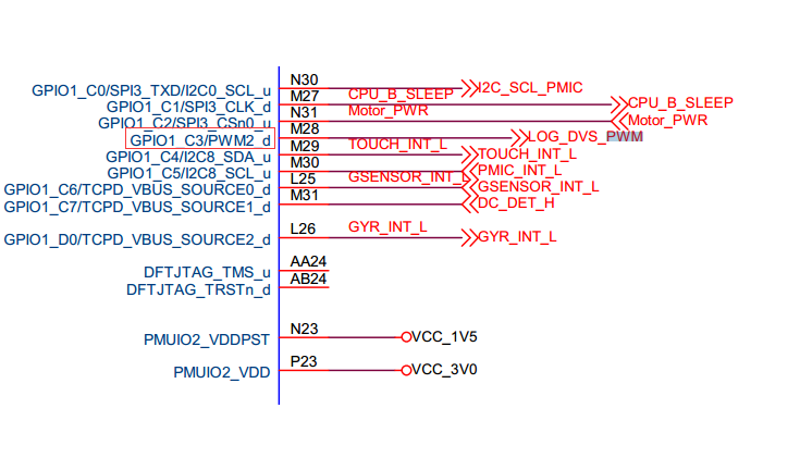
Confirm the default pull-up/pull-down of the PWM pin through the hardware schematic. For example, in the RK3399 excavator board, PWM2 is used for voltage regulation. Find the PWM2 pin in the schematic: GPIO1_C3/PWM2_d, where "d" indicates the default pull-down; if it is "u", it indicates the default pull-up.
 Define PWM pull-down pinctrl in dtsi:
pwm2_pin_pull_down: pwm2-pin-pull-down {
    rockchip,pins =
        <1 19 RK_FUNC_1 &pcfg_pull_down>;
};
In the dts, overwrite the pinctrl of PWM:
&pwm2 {
    status = "okay";
    pinctrl-names = "active";
    pinctrl-0 = <&pwm2_pin_pull_down>;
};
4.3 Unable to Measure PWM Waveform with Oscilloscope
If the oscilloscope cannot test the waveform, check from two aspects:
- First, check whether the value of the PWM Counter Register is changing. If it is changing, it means PWM is working (Note: If you use the io command to read the register, in the product document table, RK3328 and later chips need to turn off the pclk gating, because the pclk and working clock of these chips are separate); if the value of this register does not change, it means PWM is not working. Generally, these exceptions are divided into the following aspects:
- Clock issues;
- PWM register configuration issues, PWM not enabled or duty value greater than period, etc.;
- RK3368 chip requires additional configuration of bit12 in GRF_SOC_CON15 register in GRF.
- If the value of the Counter Register read is changing, it means PWM is working normally, but the signal is still not measurable, it is likely a pin issue, generally also divided into the following possible reasons:
- IOMUX issues;
- IO-domain configuration is incorrect;
- Interference from external hardware.