
Pinctrl
Chip Names and Kernel Versions
| Chip Name | Kernel Version |
|---|---|
| RK3568/RK3399/RK3368/RK3288/PX30/RK3128/RK3126/RV1126 | Linux-4.19 |
| RK3588/RV1106 | Linux-5.10 |
Introduction
Overview
This document introduces the Rockchip PIN-CTRL driver and DTS usage methods.
Target Audience
This document is primarily intended for the following engineers:
- Technical Support Engineers
- Software Development Engineers
1. Pin Naming Rules
The Rockchip Pin ID is composed of Controller(bank)+Port(port)+Index Number(pin).
1.1 GPIO (General Purpose Input/Output)
The number of controllers matches the number of GPIO controllers,
ports are fixed as A, B, C, and D,
index numbers are fixed as 0, 1, 2, 3, 4, 5, 6, 7.
For example, in RK3588, as shown in Chapter 20 GPIO of RK3588-TRM.pdf,
There are five GPIOs (GPIO0 in PD_PMU,GPIO1/GPIO2/GPIO3/GPIO4 in PD_BUS)
there are 5 GPIO controllers, each controller can control 32 IOs. When functioning as GPIO, the port behavior is configured by GPIO controller registers.
1.2 IOMUX (Input/Output Multiplexing)
Rockchip Pin can be multiplexed into multiple functions. If there are multiple multiplexed pins for the same controller, they are generally named m0, m1, m2, etc. For example, the I2C controller has two sets of multiplexed pins, namely 2cm0 and i2cm1.
The registers for pin multiplexing configuration are in GRF/PMUGRF (called IOC in RK3588).
For example, the IOMUX of RK3588 BUS_IOC_GPIO1B_IOMUX_SEL_H Address: Operational Base + offset (0x002C):
- gpio1b7_sel
- 4'h0: GPIO
- 4'h2: MIPI_CAMERA2_CLK_M0
- 4'h3: SPDIF1_TX_M0
- 4'h4: PCIE30X2_PERSTN_M3
- 4'h5: HDMI_RX_CEC_M2
- 4'h6: SATA2_ACT_LED_M1
- 4'h9: I2C5_SDA_M3
- 4'ha: UART1_RX_M1
- 4'hb: PWM13_M2
The following is the IOMUX of RK3588 I2C5:
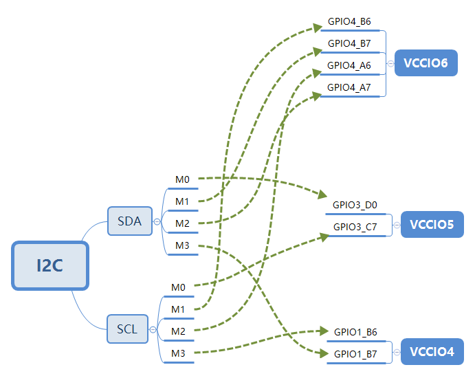 Multi-path multiplexing supports more flexible hardware design. When the working voltage of the peripheral is 1.8V or 3.3V, pins with different voltage domains VCCIO can be selected.
Note: The register configuration for multi-path multiplexing does not apply to TX-type pins, but takes effect on RX-type pins.
1.3 PULL (Port Pull-up/Pull-down)
The bias of Rockchip IO PAD generally supports 3 modes:
- bias-disable
- bias-pull-up
- bias-pull-down
The pull-up/pull-down configuration acts on the IO PAD and is effective for both GPIO and IOMUX.
1.4 DRIVE-STRENGTH (Port Drive Strength)
The drive strength of Rockchip IO PAD supports different strength configurations based on different processes. For chips before RK3399, the drive strength is configured in mA; for chips after RK1808, it is generally configured in levels, with the value of the gear directly corresponding to the register configuration.
For example, the drive strength levels of GPIO0_C7 in RK3588 TRM are as follows:
- gpio0c7_ds
- GPIO0C7 DS control Driver Strength Selection
- 3'b000: 100ohm
- 3'b100: 66ohm
- 3'b010: 50ohm
- 3'b110: 40ohm
- 3'b001: 33ohm
- 3'b101: 25ohm
- GPIO0C7 DS control Driver Strength Selection
The software driver still processes according to the level, that is, the above register description corresponds to:
- 3'b000: Level0
- 3'b100: Level4
- 3'b010: Level2
- 3'b110: Level6
- 3'b001: Level1
- 3'b101: Level5
In DTS, drive-strength=<5>; means configuring it to Level5, that is, writing 3'b101 to the register.
1.5 SMT (Port Schmitt Trigger)
Most Rockchip IO PAD chips support SMT function, which is disabled by default. Enabling SMT can eliminate edge jitter, increase the voltage range of VIH VIL, and enhance the signal stability of IO. Generally, the SCL/SDA of I2C will default to enabling the SMT function.
2. Driver Introduction
The Rockchip pinctrl driver includes the Pinctrl driver (drivers/pinctrl/pinctrl-rockchip.c) and the GPIO driver (drivers/gpio/gpio-rockchip.c).
The Pinctrl driver is the main driver, providing a method set for IO, including PINMUX, PINCONF, and GPIO.
The GPIO driver completes the functions of gpiochip, including GPIO and IRQ.
2.1 pinctrl-rockchip
//TO-DO
2.2 gpio-rockchip
//TO-DO
3. DTS Introduction
Rockchip dts generally places the pinctrl node in soc.dtsi, such as rk3588s.dtsi, usually located at the last node.
The pinctrl node does not have a reg; it is not a standard platform device. The register base value is passed in through rockchip,grf=<&grf>;; the driver internally configures IOMUX and PINCONF by adding offset addresses based on this base value; GPIO uses the reg address of the gpio node.
For example, arch/arm64/boot/dts/rockchip/rk3588s.dtsi:
{
    pinctrl: pinctrl {
        compatible = "rockchip,rk3588-pinctrl";
        rockchip,grf = <&ioc>;
        #address-cells = <2>;
        #size-cells = <2>;
        ranges;
        gpio0: gpio@fd8a0000 {
            compatible = "rockchip,gpio-bank";
            reg = <0x0 0xfd8a0000 0x0 0x100>;
            interrupts = <GIC_SPI 277 IRQ_TYPE_LEVEL_HIGH>;
            clocks = <&cru PCLK_GPIO0>, <&cru DBCLK_GPIO0>;
            gpio-controller;
            #gpio-cells = <2>;
            interrupt-controller;
            #interrupt-cells = <2>;
        };
        gpio1: gpio@fec20000 {
            compatible = "rockchip,gpio-bank";
            reg = <0x0 0xfec20000 0x0 0x100>;
            interrupts = <GIC_SPI 278 IRQ_TYPE_LEVEL_HIGH>;
            clocks = <&cru PCLK_GPIO1>, <&cru DBCLK_GPIO1>;
            gpio-controller;
            #gpio-cells = <2>;
            interrupt-controller;
            #interrupt-cells = <2>;
        };
        gpio2: gpio@fec30000 {
            compatible = "rockchip,gpio-bank";
            reg = <0x0 0xfec30000 0x0 0x100>;
            interrupts = <GIC_SPI 279 IRQ_TYPE_LEVEL_HIGH>;
            clocks = <&cru PCLK_GPIO2>, <&cru DBCLK_GPIO2>;
            gpio-controller;
            #gpio-cells = <2>;
            interrupt-controller;
            #interrupt-cells = <2>;
        };
        gpio3: gpio@fec40000 {
            compatible = "rockchip,gpio-bank";
            reg = <0x0 0xfec40000 0x0 0x100>;
            interrupts = <GIC_SPI 280 IRQ_TYPE_LEVEL_HIGH>;
            clocks = <&cru PCLK_GPIO3>, <&cru DBCLK_GPIO3>;
        };
        gpio4: gpio@fec50000 {
            compatible = "rockchip,gpio-bank";
            reg = <0x0 0xfec50000 0x0 0x100>;
            interrupts = <GIC_SPI 281 IRQ_TYPE_LEVEL_HIGH>;
            clocks = <&cru PCLK_GPIO4>, <&cru DBCLK_GPIO4>;
            gpio-controller;
            #gpio-cells = <2>;
            interrupt-controller;
            #interrupt-cells = <2>;
        };
    };
};
The arch/arm64/boot/dts/rockchip/rk3588s-pinctrl.dtsi file is then included in rk3588s.dtsi.
3.1 Creating a New pinctrl
The rk3588s-pinctrl.dtsi file has enumerated all the instances of iomux for the rk3588s chip. Generally, modules do not need to create iomux instances; if iomux instances need to be created, the following rules must be followed:
- Must be under the pinctrl node
- Must be added in the form of function+group
- The format of function+group is as follows
function {
    group {
    rockchip,pin = <bank gpio func &ref>;
    };
}; - Follow other basic rules of dts
3.2 Referencing pinctrl
Modules reference pinctrl through pinctrl-names and pinctrl-0, connecting the module and pinctrl driver.
For example, rk3588 uart2:
{
    uart2: serial@feb50000 {
        compatible = "rockchip,rk3588-uart", "snps,dw-apb-uart";
        reg = <0x0 0xfeb50000 0x0 0x100>;
        interrupts = <GIC_SPI 333 IRQ_TYPE_LEVEL_HIGH>;
        clocks = <&cru SCLK_UART2>, <&cru PCLK_UART2>;
        clock-names = "baudclk", "apb_pclk";
        reg-shift = <2>;
        reg-io-width = <4>;
        dmas = <&dmac0 10>, <&dmac0 11>;
        pinctrl-names = "default";
        pinctrl-0 = <&uart2m1_xfer>;
        status = "disabled";
    };
};
uart2m1_xfer is a pinctrl group; a module can reference multiple groups simultaneously.
For example, rk3588 pdm1:
{
    pdm1: pdm@fe4c0000 {
        compatible = "rockchip,rk3588-pdm";
        reg = <0x0 0xfe4c0000 0x0 0x1000>;
        clocks = <&cru MCLK_PDM1>, <&cru HCLK_PDM1>;
        clock-names = "pdm_clk", "pdm_hclk";
        assigned-clocks = <&cru MCLK_PDM1>;
        assigned-clock-parents = <&cru PLL_AUPLL>;
        dmas = <&dmac1 4>;
        dma-names = "rx";
        power-domains = <&power RK3588_PD_AUDIO>;
        pinctrl-names = "default";
        pinctrl-0 = <&pdm1m0_clk
            &pdm1m0_clk1
            &pdm1m0_sdi0
            &pdm1m0_sdi1
            &pdm1m0_sdi2
            &pdm1m0_sdi3>;
        /* 等同于如下写法 */
        /*
         * pinctrl-0 = <&pdm1m0_clk>,
         *     <&pdm1m0_clk1>,
         *     <&pdm1m0_sdi0>,
         *     <&pdm1m0_sdi1>,
         *     <&pdm1m0_sdi2>,
         *     <&pdm1m0_sdi3>;
         */
        #sound-dai-cells = <0>;
        status = "disabled";
    };
};
pinctrl-names can support multiple instances, and there are 4 default instances (states) for pinctrl:
PINCTRL_STATE_DEFAULT:"default"PINCTRL_STATE_INIT:"init"PINCTRL_STATE_IDLE:"idle"PINCTRL_STATE_SLEEP:"sleep"
pinctrl-names can be customized and matched and parsed by the driver.
For example, rk3588 pwm4:
{
    pwm4: pwm@febd0000 {
        compatible = "rockchip,rk3588-pwm", "rockchip,rk3328-pwm";
        reg = <0x0 0xfebd0000 0x0 0x10>;
        #pwm-cells = <3>;
        pinctrl-names = "active";
        pinctrl-0 = <&pwm4m0_pins>;
        clocks = <&cru CLK_PWM1>, <&cru PCLK_PWM1>;
        clock-names = "pwm", "pclk";
        status = "disabled";
    };
};
4. FAQ
4.1 User-level Configuration IOMUX
IOMUX is a binary file compiled by gcc. You can set the IOMUX by calling the rockchip-pinctrl device through ioctl, and you can also get the current value of the IOMUX.
Compilation method:
gcc tools/testing/selftests/rkpinctrl/iomux.c -o iomux
Usage method:
For example: set GPIO0_B7 to func1
[root@RK3588:/]# iomux 0 15 1
For example: get the current IOMUX value of GPIO0_B7
[root@RK3588:/]# iomux 0 15
mux get (GPIO0-15) = 1
4.2 Configuring the Level of a GPIO
There is a specific requirement where a GPIO does not belong to a particular module, but is more of a power switch, and it is希望在系统开机过程中尽快输出高或低电平,要怎么实现呢?
Use "regulator-fixed".
regulator-fixed is usually used to define a regulator with a fixed voltage, or a regulator controlled by a GPIO.
For example, GPIO2_A1 needs to be configured as high:
/ {
    foo_name: foo-name {
        compatible = "regulator-fixed";
        pinctrl-names = "default";
        pinctrl-0 = <&gpio_foo>;
        regulator-name = "vcc-foo";
        regulator-always-on;
    };
};
&pinctrl {
    gpio-foo {
        gpio_foo: gpio-foo {
            rockchip,pins = <2 RK_PA1 RK_FUNC_GPIO &pcfg_output_high>;
        };
    };
};
4.3 The pinctrl-0 of the Module Does Not Take Effect
Usually, the module calls pinctrl-names pinctrl-0 to configure the default IOMUX or IOCONFIG, but not all nodes can have these two attributes. If the module is called by driver_probe_device, it can have these two attributes.
Debug method: Add print statements in pinctrl_bind_pins in drivers/base/dd.c to observe the call.