
I2C
Chip Names and Kernel Versions
| Chip Name | Kernel Version |
|---|---|
| All chips | All versions |
Introduction
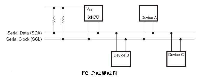
The ROCKCHIP series chips provide standard I2C bus to facilitate customer control and access to different external devices. The I2C bus controller transfers information between devices connected to the bus through the serial data (SDA) line and serial clock (SCL) line. Each device has a unique address identifier (whether it's a microcontroller—MCU, LCD driver, memory, or keyboard interface) and can act as either a transmitter or receiver (determined by the device's function).
Rockchip I2C controller supports the following features:
- Compatible with I2C and SMBus bus
- Only supports I2C bus in master mode
- Software programmable clock frequency support up to 400kbps, some chips can be as high as 1000kbps
- Supports 7-bit and 10-bit addressing modes
- Interrupt or polling for up to 32 bytes of data transmission
The following diagram shows the hardware connection of the I2C bus, pull-up resistors are required, and changing the size of the pull-up resistors can adjust the pull-up strength of the I2C bus.
ROCKCHIP I2C drivers vary across different chips and kernel versions: i2c-rk3x.c or i2c-rockchip.c (i2c-rockchip.c driver is used in kernel version 3.10), the highest frequency at which I2C can operate is generally 1000K.
Intended Audience
This document is mainly suitable for the following engineers:
- Technical support engineers
- Software development engineers
1. I2C Process
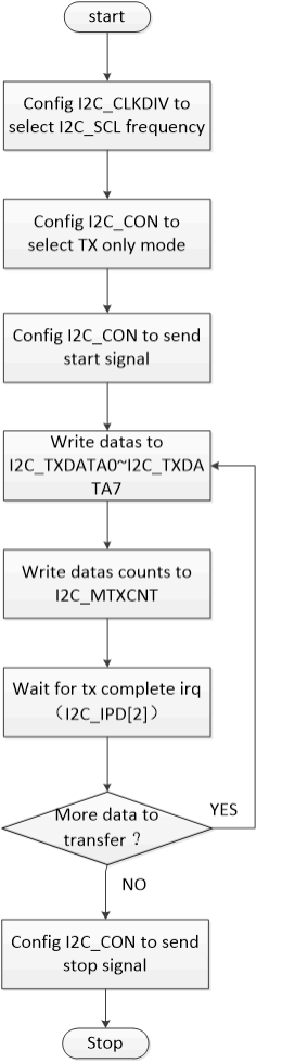
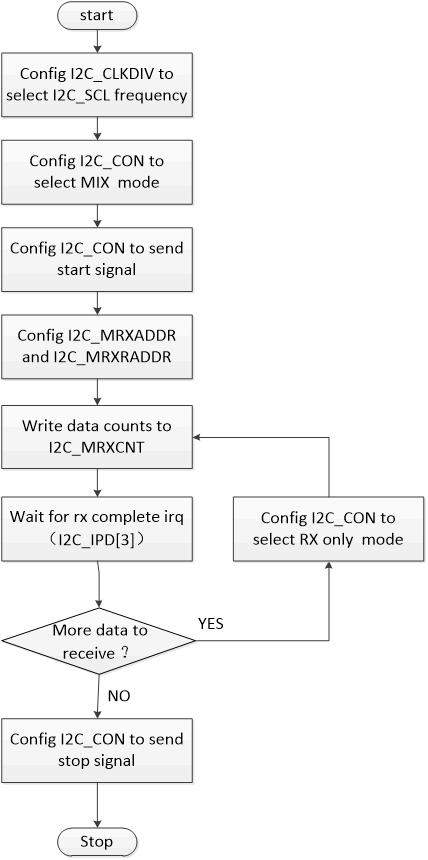
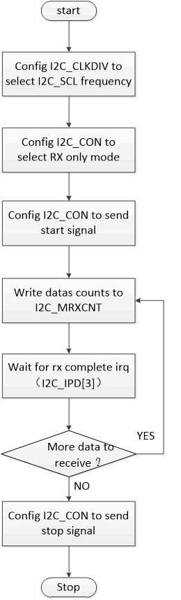
The I2C process is roughly the same across the two drivers, writing is purely in TX mode (I2C_CON[1:0]=2’b00), while reading generally uses TRX mode (I2C_CON[1:0]=2’b01). The following flowcharts describe how software configures and executes I2C tasks through the I2C controller registers. The description is divided into three parts: transmission mode, mixed mode, and reception mode.
1.1 Transmission Only Mode (I2C_CON[1:0]=2’b00)
1.2 Mixed Mode (I2C_CON[1:0]=2’b01 or I2C_CON[1:0]=2’b11)
1.3 Reception Only Mode (I2C_CON[1:0]=2’b10)
The above describes the main processes of I2C, for detailed implementation refer to the driver code.
2. I2C Driver Parameter Configuration
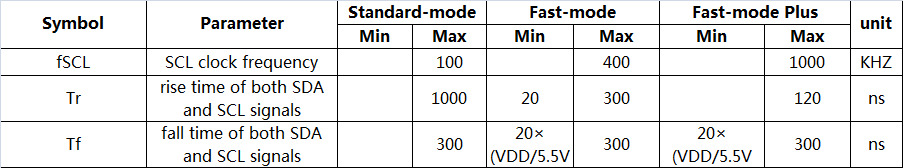
The most important parameter configuration for I2C is the I2C frequency, the configurable I2C frequency is determined not only by the chip but also by the I2C SCL rise time, because the I2C protocol standard specifies the timing requirements for the rising and falling edges, especially the rising edge time, if it exceeds the maximum value specified by the protocol, I2C communication may fail, the following diagram shows the relationship between the two:
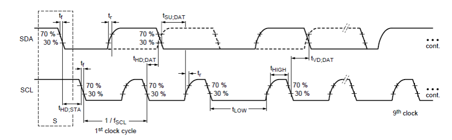
The rise time Tr and fall time Tf need to be measured with an oscilloscope, refer to the following diagram:
The configuration methods for the two drivers i2c-rk3x.c and i2c-rockchip.c are different, as follows:
2.1 i2c-rk3x.c Configuration
The configuration for the i2c-rk3x.c driver is done in the DTS, refer to the file Documentation/devicetree/bindings/i2c/i2c-rk3x.txt. Key configuration items include i2c-scl-rising-time-ns, i2c-scl-falling-time-ns:
clock-frequency: default frequency is 100k and does not need to be configured, other I2C frequencies need to be configured, the maximum configurable frequency is determined byi2c-scl-rising-time-ns; for example, to configure 400k, useclock-frequency=<400000>.i2c-scl-rising-time-ns: SCL rising edge time is determined by hardware, changing the pull-up resistor can adjust this time, and it needs to be measured with an oscilloscope, refer to the above diagram; for example, if the SCL rising edge is measured at 365ns, usei2c-scl-rising-time-ns=<365>.(It can be left unconfigured by default, but it must be ensured that the current rising edge time does not exceed the maximum rising edge time defined by the I2C standard at the configured frequency)i2c-scl-falling-time-ns: SCL falling edge time, generally unchanged, equivalent toi2c-sda-falling-time-ns.(It can also be left unconfigured by default)
Example:
&i2c1 {
 status = "okay";
 i2c-scl-rising-time-ns = <265>;
 i2c-scl-falling-time-ns = <11>;
 clock-frequency = <400000>;
 es8316: es8316@10 {
 #sound-dai-cells = <0>;
 compatible = "everest,es8316";
 reg = <0x10>;
 clocks = <&cru SCLK_I2S_8CH_OUT>;
 clock-names = "mclk";
 spk-con-gpio = <&gpio0 11 GPIO_ACTIVE_HIGH>;
 hp-det-gpio = <&gpio4 28 GPIO_ACTIVE_LOW>;
 };
};
2.2 i2c-rockchip.c Configuration
The i2c-rockchip.c driver still follows the constraint relationship between I2C frequency and SCL rising edge, whether a higher frequency can be used depends on i2c-scl-rising-time-ns; the I2C frequency is configured in the code by directly setting the scl_rate member of the i2c_msg structure, the default frequency is still 100k, for example, the following 200K configuration:
struct i2c_msg xfer_msg;
xfer_msg[0].addr = client->addr;
xfer_msg[0].len = num;
xfer_msg[0].flags = client->flags;
xfer_msg[0].buf = buf;
xfer_msg[0].scl_rate = 200 * 1000; /* 200K i2c clock frequency */
3. Using I2C
For instructions on using I2C, please refer to Documentation/i2c/ which has detailed information, below are the key points for the read and write sections:
3.1 Kernel Space
The read and write communication of Rockchip I2C uses the standard Linux interface, please refer to the Documentation/i2c/writing-clients document under the kernel, the "Sending and receiving" section inside has a systematic introduction.
3.2 User Space
Usually, I2C devices are controlled by kernel drivers. But it is also possible to access all devices on the bus from user space, through the /dev/i2c-%d interface, the Documentation/i2c/dev-interface document under the kernel has detailed instructions and examples.
4. I2C Tools
I2C tool is an open-source tool that needs to be downloaded and cross-compiled by yourself, the code download address:
- https://www.kernel.org/pub/software/utils/i2c-tools/
<git clone git://git.kernel.org/pub/scm/utils/i2c-tools/i2c-tools.git>
After compilation, tools like i2cdetect, i2cdump, i2cset, i2cget will be generated, which can be directly used in the command line for debugging:
i2cdetect– used to list I2C bus and all devices on iti2cdump– displays the values of all registers of the i2c devicei2cget– reads the value of a specific register of the i2c devicei2cset– writes a value to a specific register of the i2c device
I2C tool is open-source, for compilation and usage, please refer to its README and help instructions.
5. GPIO Simulated I2C
I2C can be simulated with GPIO, the kernel has implemented this, please refer to the document: Documentation/devicetree/bindings/i2c/i2c-gpio.txt
Below is an example of using it, configuring the I2C node in the dts:
i2c@4 {
    compatible = "i2c-gpio";
    gpios = <&gpio5 9 GPIO_ACTIVE_HIGH>, /* sda */
            <&gpio5 8 GPIO_ACTIVE_HIGH>; /* scl */
    i2c-gpio,delay-us = <2>;       /* ~100 kHz */
    #address-cells = <1>;
    #size-cells = <0>;
    pinctrl-names = "default";
    pinctrl-0 = <&i2c4_gpio>;
    status = "okay";
    gt9xx: gt9xx@14 {
        compatible = "goodix,gt9xx";
        reg = <0x14>;
        touch-gpio = <&gpio5 11 IRQ_TYPE_LEVEL_LOW>;
        reset-gpio = <&gpio5 10 GPIO_ACTIVE_HIGH>;
        max-x = <1200>;
        max-y = <1900>;
        tp-size = <911>;
        tp-supply = <&vcc_tp>;
        status = "okay";
    };
};
Generally, using GPIO is not recommended due to low efficiency.
6. Common I2C Issues
Since we have two i2c drivers, we will still divide into two parts:
6.1 i2c-rk3x.c Driver
If the return value of the I2C transmission interface is -6 (-ENXIO), it indicates a NACK error, meaning no response from the device, this is generally a peripheral issue, common situations include:
- Incorrect I2C address;
- I2C slave device not in normal working condition, such as not powered, incorrect power-up sequence, or device malfunction, etc;
- I2C timing does not meet the requirements of the slave device, which may also generate NACK signal, for example, when the slave device requires a stop signal instead of a repeat start signal;
- I2C bus interference from external sources, which can be seen as an ACK waveform when measured with an oscilloscope.
When the I2C log shows: "timeout, ipd: 0x00, state: 1", the I2C controller is abnormally working and cannot generate interrupt status, and the start timing cannot be issued, there are the following possible reasons:
- I2C SCL or SDA pin iomux error;
- Incorrect pull-up voltage for I2C, such as insufficient voltage or pull-up power not connected;
- I2C pin being pulled by the peripheral, causing incorrect voltage;
- I2C clock not enabled, or clock source too weak;
- I2C CON_START and CON_STOP bits are configured simultaneously.
When the I2C log shows: "timeout, ipd: 0x10, state: 1", the I2C controller is working normally, but the CPU cannot respond to the I2C interrupt, this may be because cpu0 is blocked (generally, I2C interrupts are on cpu0, which can be checked by cat /proc/interrups), or the I2C interrupt bit may be turned off.
When the I2C log shows something like "timeout, ipd: 0x80, state: 1", and ipd is 0x80, it can be concluded that the current SCL is被 slave 拉住, to determine which slave is pulling it down:
- One is the elimination method, suitable for situations with few peripherals and high reproduction probability;
- The second is to modify the hardware, insert a resistor in series on the SCL bus, and determine by the voltage difference across the resistor which side has a lower voltage, that side is the slave pulling the line down, the resistor should be selected so as not to affect I2C transmission and can show the voltage difference, generally, more than 1/20 of the pull-up resistor value is sufficient, if the host is pulling it down, it can also be seen. Additionally, capturing the waveform with an oscilloscope can more intuitively compare the low-level voltages of different slaves and the host, and compare with the low-level voltage at the time of the problem, the one that matches is the "culprit" pulling down the bus.
Commonly, if SDA is pulled low, it can be identified by the above two methods for "SCL being pulled low".
6.2 i2c-rockchip.c Driver
If the return value of the I2C transmission interface is -11 (-EAGAIN), it indicates a NACK error, meaning no response from the device, this is generally a peripheral issue, common situations include:
- Incorrect I2C address;
- I2C slave device not in normal working condition, such as not powered, incorrect power-up sequence, or device malfunction, etc;
- I2C timing does not meet the requirements of the slave device, which may also generate NACK signal, for example, when the slave device requires a stop signal instead of a repeat start signal;
- I2C bus interference from external sources, which can be seen as an ACK waveform when measured with an oscilloscope.
When the I2C log shows: "timeout, ipd: 0x00, state: 1", the I2C controller is abnormally working and cannot generate interrupt status, and the start timing cannot be issued, there are the following possible reasons:
- I2C SCL or SDA pin iomux error;
- Incorrect pull-up voltage for I2C, such as insufficient voltage or pull-up power not connected;
- I2C pin being pulled by the peripheral, causing incorrect voltage;
- I2C clock not enabled, or clock source too weak;
- I2C CON_START and CON_STOP bits are configured simultaneously.
When the I2C log shows: "timeout, ipd: 0x10, state: 1", the I2C controller is working normally, but the CPU cannot respond to the I2C interrupt, this may be because cpu0 is blocked (generally, I2C interrupts are on cpu0, which can be checked by cat /proc/interrups), or the I2C interrupt bit may be turned off.
When the I2C log shows something like "timeout, ipd: 0x80, state: 1", and ipd is 0x80, or "scl was hold by slave" is printed, it can be concluded that the current SCL is被 slave 拉住, to determine which slave is pulling it down:
- One is the elimination method, suitable for situations with few peripherals and high reproduction probability;
- The second is to modify the hardware, insert a resistor in series on the SCL bus, and determine by the voltage difference across the resistor which side has a lower voltage, that side is the slave pulling the line down, the resistor should be selected so as not to affect I2C transmission and can show the voltage difference, generally, more than 1/20 of the pull-up resistor value is sufficient, if the host is pulling it down, it can also be seen. Additionally, capturing the waveform with an oscilloscope can more intuitively compare the low-level voltages of different slaves and the host, and compare with the low-level voltage at the time of the problem, the one that matches is the "culprit" pulling down the bus.
Commonly, if SDA is pulled low, it can be identified by the above two methods for "scl was hold by slave".
When the log shows "i2c is not in idle(state = ×)", it indicates that at least one of the I2C bus lines is low, refer to the above methods to resolve:
- "state=1" indicates SDA is low;
- "state=2" indicates SCL is low;
- "state=3" indicates both SCL and SDA are low。
6.3 Debugging I2C Waveforms
If the I2C issues do not fall into the above categories, the best way to troubleshoot is to capture the waveform when the I2C error occurs, most issues can be analyzed through the I2C waveform; you can make the CPU hang at the error point (for example, while(1) etc.), without initiating new I2C tasks, the last captured waveform should be the erroneous waveform, if filtering is needed, you can also add conditions like the device I2C address.