
HDMI
Chip Name and Kernel Version
- Chip Name: RK322X/RK3328/RK3368/RK3399/RK3288/RK3528/RK356X/RK3588
- Kernel Version: LINUX kernel 6.1/5.10/4.19/4.4
Preface
This document mainly introduces the usage and debugging methods of HDMI based on the DRM display framework on the Rockchip platform.
Overview
Product Versions
- RK3288
- RK3368
- RK322X
- RK3328
- RK3399
- RK3528
- RK356X
- RK3588
- RK3576
Target Audience
- Technical Support Engineers
- Software Development Engineers
1. Introduction to HDMI on Rockchip Platform
The HDMI functions of various Rockchip platforms are as follows:
| Function | RK3288 | RK3368 | RK322X | RK3328 | RK3399 | RK3528 | RK356X | RK3588 | RK3576 |
|---|---|---|---|---|---|---|---|---|---|
| Max Output Resolution | 3840x2160p60 | 4096x2160p60 | 4096x2160p60 | 4096x2160p60 | 4096x2160p60 | 4096x2160p60 | 4096x2160p60 | 7680x4320p60 | 4096x2160p120 |
| Interlaced Mode | N | N | Y | Y | Y | Y | Y | Y | Y |
| Supported Color Formats | RGB, YCbCr444, YCbCr422, YCbCr420 (YCbCr420 only supported by RK3288W) | RGB, YCbCr444, YCbCr422, YCbCr420 | RGB, YCbCr444, YCbCr422, YCbCr420 | RGB, YCbCr444, YCbCr422, YCbCr420 | RGB, YCbCr444, YCbCr420 | RGB, YCbCr444, YCbCr422, YCbCr420 | RGB, YCbCr444, YCbCr422, YCbCr420 | RGB, YCbCr444, YCbCr422, YCbCr420 | RGB, YCbCr444, YCbCr422, YCbCr420 |
| 10bit Color Depth Support | Y | N | Y | Y | Y | Y | Y | Y | Y |
| Supported HDMI Protocol | HDMI 2.0 | HDMI 2.0 | HDMI 2.0 | HDMI 2.0 | HDMI 2.0 | HDMI 2.0 | HDMI 2.0 | HDMI 2.1 | HDMI 2.1 |
DRM: DRM stands for Direct Rendering Manager, which is a component of the DRI (Direct Rendering Infrastructure) framework. LINUX kernel 4.4 and later use the DRM framework. The HDMI driver paths are:
kernel/drivers/gpu/drm/rockchip/dw_hdmi-Rockchip.c
kernel/drivers/gpu/drm/rockchip/inno_hdmi.c
kernel/drivers/gpu/drm/bridge/synopsys/
2. Introduction to HDMI in the DRM Framework
2.1 HDMI Software Function Configuration
2.1.1 Enable HDMI
To enable HDMI, add:
&hdmi {
    status = "okay";
};
2.1.2 Bind VOP
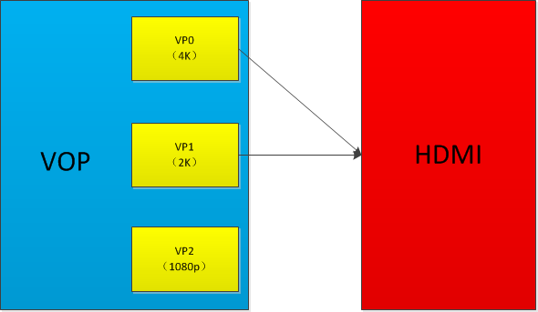
On Rockchip platforms, the image data output by various display interfaces (HDMI, DP, CVBS, etc.) comes from VOP:

If the platform has two VOPs (RK3288, RK3399): VOPB (supports 4K), VOPL (supports only 2K), the two VOPs can be bound to two display interfaces respectively (one display interface can only be bound to one VOP), and can be swapped:

- When the display device node is enabled in DTS, the ports of VOPB and VOPL corresponding to the display interface will be enabled, so you need to disable the port of the unused VOP.
For example, to bind HDMI to VOPB, add:
&hdmi_in_vopl {
    status = "disabled";
};
Conversely, to bind to VOPL, add:
&hdmi_in_vopb {
 status = "disabled";
};
If the platform has only one VOP, this step is not required.
VOP2 and later versions: There is no longer more than one VOP on a platform. Instead, there is only one VOP, and there are multiple VPs (Video Ports) in the VOP for output.
-
RK356X VOP and HDMI Path:
- HDMI can be bound to VP0 or VP1. It is recommended to bind to VP0 to support 4K output:
&hdmi_in_vp0 {
    status = "okay";
};
&hdmi_in_vp1 {
    status = "disabled";
};
- HDMI can be bound to VP0 or VP1. It is recommended to bind to VP0 to support 4K output:
-
RK3588 VOP and HDMI Path:
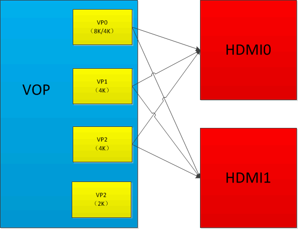
- RK3588 has two HDMITX, both are identical in performance and can be bound to VP0/1/2 respectively.
- If only up to 4K resolution output is required, it is recommended to bind HDMI0/1 to VP0/1 respectively:
        &hdmi0_in_vp0 {
    status = "okay";
    };
    &hdmi0_in_vp1 {
    status = "disabled";
    };
    &hdmi0_in_vp2 {
    status = "disabled";
    };
    &hdmi1_in_vp1 {
    status = "okay";
    };
    &hdmi1_in_vp0 {
    status = "disabled";
    };
    &hdmi1_in_vp2 {
    status = "disabled";
    };
-
RK3588 platform requires 8K output: VP0 and VP1 ports must be used for stitching. In DTS, HDMI outputting 8K must be bound to VP0, for example, HDMI0:
  &hdmi0_in_vp0 {
  status = "okay";
  };
  &hdmi0_in_vp1 {
  status = "disabled";
  };
  &hdmi0_in_vp2 {
  status = "disabled";
  };
At the same time, VOP ACLK needs to be set to 800M, see 3.1.4.
-
RK3588 HDMI and eDP share COMBPHY, for example, HDMI0 and eDP0. In DTS,
hdptxphy_hdmi0is the HDMI PHY node, andhdptxphy0is the eDP PHY node:hdptxphy0: phy@fed60000 {
compatible = "rockchip,rk3588-hdptx-phy";
reg = <0x0 0xfed60000 0x0 0x2000>;
clocks = <&cru CLK_USB2PHY_HDPTXRXPHY_REF>, <&cru PCLK_HDPTX0>;
clock-names = "ref", "apb";
resets = <&cru SRST_P_HDPTX0>, <&cru SRST_HDPTX0_INIT>,
<&cru SRST_HDPTX0_CMN>, <&cru SRST_HDPTX0_LANE>;
reset-names = "apb", "init", "cmn", "lane";
rockchip,grf = <&hdptxphy0_grf>;
#phy-cells = <0>;
status = "disabled";
};
hdptxphy_hdmi0: hdmiphy@fed60000 {
compatible = "rockchip,rk3588-hdptx-phy-hdmi";
reg = <0x0 0xfed60000 0x0 0x2000>;
clocks = <&cru CLK_USB2PHY_HDPTXRXPHY_REF>, <&cru PCLK_HDPTX0>;
clock-names = "ref", "apb";
clock-output-names = "clk_hdmiphy_pixel0";
#clock-cells = <0>;
resets = <&cru SRST_HDPTX0>, <&cru SRST_P_HDPTX0>,
<&cru SRST_HDPTX0_INIT>, <&cru SRST_HDPTX0_CMN>,
<&cru SRST_HDPTX0_LANE>, <&cru SRST_HDPTX0_ROPLL>,
<&cru SRST_HDPTX0_LCPLL>;
reset-names = "phy", "apb", "init", "cmn", "lane", "ropll",
"lcpll";
rockchip,grf = <&hdptxphy0_grf>;
#phy-cells = <0>;
status = "disabled";
};
Therefore, when using HDMI, you must disable the corresponding eDP and eDP PHY. For example, HDMI0:
&hdmi0 {
 status = "okay";
};
&hdptxphy_hdmi0 {
 status = "okay";
};
&edp0 {
 status = "disabled";
};
&hdptxphy0 {
 status = "disabled";
};
2.1.3 Enable Boot Logo
If the U-Boot logo is not enabled, the kernel stage cannot display the boot logo, and you can only see the application image after the system starts. Enable route_hdmi in DTS to enable U-Boot logo support:
&route_hdmi {
    status = "okay";
};
On dual VOP platforms, note that the connect in the code must specify the same VOP as the one bound to HDMI (see 3.1.2), otherwise there may be display issues.
route_hdmi: route-hdmi {
    status = "disabled";
    logo,uboot = "logo.bmp";
    logo,kernel = "logo_kernel.bmp";
    logo,mode = "center";
    charge_logo,mode = "center";
    connect = <&vopb_out_hdmi>;
};
2.1.4 VOP dclk Bind PLL
The VOP/VP dclk bound to HDMI needs to specify the corresponding PLL as the clock source. On RK platforms, RK322X/RK3328/RK3528 HDMI are all bound to a fixed VOP/VP and use the HDMI PHY PLL as the dclk clock source, no configuration required.
2.1.4.1 RK3288 Bind PLL
RK3288 VOPB/VOPL dclk can be attached to GPLL/CPLL. Since these two PLLs do not support fractional division, RK3288 HDMI can only output standard resolutions with integer division of 594M (such as 4K60/1080P60/720P60). For example, VOPB dclk attached to GPLL, VOPL dclk attached to CPLL:
&vopb {
    assigned-clocks = <&cru DCLK_VOP0>;
    assigned-clock-parents = <&cru PLL_GPLL>;
};
&vopl {
    assigned-clocks = <&cru DCLK_VOP1>;
    assigned-clock-parents = <&cru PLL_CPLL>;
};
2.1.4.2 RK3399 Bind PLL
RK3399 HDMI bound VOP dclk needs to be attached to VPLL. For dual display, the other VOP dclk should be attached to CPLL, so that any frequency dclk can be generated to support dual display with any resolution. For example, when HDMI is bound to VOPB:
&vopb {
    assigned-clocks = <&cru DCLK_VOP0_DIV>;
    assigned-clock-parents = <&cru PLL_VPLL>;
};
&vopl {
    assigned-clocks = <&cru DCLK_VOP1_DIV>;
    assigned-clock-parents = <&cru PLL_CPLL>;
};
When HDMI is bound to VOPL:
&vopb {
    assigned-clocks = <&cru DCLK_VOP0_DIV>;
    assigned-clock-parents = <&cru PLL_CPLL>;
};
&vopl {
    assigned-clocks = <&cru DCLK_VOP1_DIV>;
    assigned-clock-parents = <&cru PLL_VPLL>;
};
2.1.4.3 RK356X Bind PLL
RK356X HDMI bound VP dclk must be attached to HPLL, for example, VP0 dclk:
&vop {
    assigned-clocks = <&cru DCLK_VOP0>;
    assigned-clock-parents = <&pmucru PLL_HPLL>;
};
2.1.4.4 RK3588/RK3576 Bind PLL
If RK3588 needs to output resolutions above 4K60, VOP ACLK must be set to 800MHz:
&vop {
    assigned-clocks = <&cru ACLK_VOP>;
    assigned-clock-rates = <800000000>;
    status = "okay";
};
RK3588 HDMI 0/1 can be bound to VP 0/1/2, see 2.1.2. These three VP dclk can be attached to GPLL/HDMI0 PHY PLL/HDMI 1 PHY PLL/V0PLL.
For specific allocation strategies and related restrictions, refer to section 10.11 of "Rockchip_Developer_Guide_DRM_Display_Driver_CN.pdf".
RK3588/RK3576 must specify PHY PLL as the VOP dclk clock source to support non-standard resolutions.
RK3588 DTS configuration:
&display_subsystem {
 clocks = <&hdptxphy_hdmi_clk0>, <&hdptxphy_hdmi_clk1>;
 clock-names = "hdmi0_phy_pll", "hdmi1_phy_pll";
};
&hdptxphy_hdmi_clk0 {
 status = "okay";
};
&hdptxphy_hdmi_clk1 {
 status = "okay";
};
RK3576 DTS configuration:
&display_subsystem {
 clocks = <&hdptxphy_hdmi>;
 clock-names = "hdmi0_phy_pll";
};
You can use cat /sys/kernel/debug/clk/clk_summary to confirm whether the DTS clock allocation is effective.
For example, when dclk_vop0 is bound to HDMI0 PHY PLL, dclk_vop0 is under clk_hdmiphy_pixel0 in the clock tree:
 xin24m                             26       28       0   24000000         0
    0 50000
   clk_usbdpphy_mipidcpphy_ref       2       2       0   24000000         0
    0 50000
   clk_usb2phy_hdptxrxphy_ref       11       11       0   24000000         0
    0 50000
       clk_hdmiphy_pixel0             2       3       0   594000000         0
    0 50000
         dclk_vop0                   2       4       0   594000000         0
    0 50000
2.1.5 RK3288/RK3399/RK3528/RK356X HDCP Enable
2.1.5.1 HDCP 1.4 Enable
&hdmi {
 hdcp1x-enable = <1>;
}
After enabling HDCP 1.4, the corresponding key needs to be burned through the tool, which can be obtained in the RKTools directory of the SDK. Different Android tools may vary, please consult FAE, and refer to the tool's readme for instructions. The corresponding key needs to be applied by the customer from Digital Content Protection LLC.
The HDCP function can be turned on or off through the following node:
echo 1 > /sys/class/misc/hdmi_hdcp1x/enable
1 means to turn on the HDCP function, and 0 means to turn off the HDCP function.
After turning on the HDCP function, you can confirm whether HDCP is effective through the following methods:
cat /sys/class/misc/hdmi_hdcp1x/status
Different values correspond to different HDCP states:
hdcp disable: HDCP function is off.hdcp_auth_start: HDCP authentication started.hdcp_auth_success: HDCP authentication successful, starting to transmit encrypted video data.hdcp_auth_fail: HDCP authentication failed.
Find a TV that does not support HDCP 1.4 and a TV that supports HDCP 1.4. If the TV that does not support HDCP 1.4 shows a pink screen after the HDCP function is turned on, and the TV that supports HDCP 1.4 can be displayed normally, it means HDCP is working normally.
2.1.5.2 HDCP 2.2 Enable
RK3288/RK3399/RK3528/RK356X support HDCP 2.2 function under DRM framework. It is important to ensure that HDCP 1.4 is working normally before using HDCP 2.2 function. To enable this function, the following steps are required:
- Apply to FAE for HDCP 2.2 Key packaging tool and patch package, and package the Key according to the readme.
- Recompile and flash, then use the following node to turn on/off HDCP 2.2 function:
echo 1 > /sys/class/misc/hdcp2_node/enable
After enabling, you can check whether HDCP 2.2 is working normally through the following methods:
- Find a TV that does not support HDCP 2.2 and a TV that supports HDCP 2.2. If the TV that does not support HDCP 2.2 shows a white screen after the HDCP function is turned on, and the TV that supports HDCP 2.2 can be displayed normally, it means HDCP is working normally.
You can get the HDCP 2.2 working status through the following node:
cat /sys/class/misc/hdcp2_node/status
- hdcp2 auth sucess: Authentication successful.
- no enable hdcp2: HDCP 2.2 is off.
- hdcp2 no auth: HDMI not connected or device does not support HDCP 2.2.
- no already auth sucess: Authentication failed.
If authentication fails, please upload the following log files to redmine:
/cache/hdcp_tx0.log- Or execute the following command to capture the log:
logcat -s HDMI_HDCP2
dmesg | grep hdcp
2.1.6 RK3588/RK3576 HDCP Enable
RK3588/RK3576 support HDCP 1.4/2.3, and the enabling of both requires calling the HDCP interface of the DRM framework. Turn on/off HDCP and query HDCP status through DRM PROPERTY. Related DEMO code hdcptest.c can be applied from the business. During debugging, you can use modetest for testing.
The code path for modetest in the Android system is:
external/libdrm/tests/modetest/
In the Linux system, you can use the modetest compiled by buildroot, the code path after compiling rootfs is:
buildroot/output/rockchip_rk3588/build/libdrm-2.4.115/testst/modetest/
To test HDCP with modetest, you need to use the following properties:
Content Protection:
               flags: enum
               enums: Undesired=0 Desired=1 Enabled=2
               value: 2
Undesired:Turn off hdcp
Desired:Turn on hdcp
Enabled:hdcp is already turned on and authenticated successfully
hdcp_encrypted:
               flags: range
               values: 0 2
               value: 2
hdcp authentication level:
   0:hdcp not authenticated。
   1:hdcp1.4。
   2:hdcp2.3。
The HDCP switch can be turned on or off using the command modetest -w, for example:
modetest -w 423:"Content Protection":1
  ------->Turn on hdcp, prioritize 2.3, if the TV does not support 2.3 or 2.3 authentication fails, automatically switch to 1.4.
  modetest -w 423:"Content Protection":0
  ------->Turn off hdcp.
Where 423 is the connector id of HDMI, you can use the command modetest -c to query:
     rk3588_s:/ # modetest -c
trying to open device 'i915'...failed
trying to open device 'amdgpu'...failed
trying to open device 'radeon'...failed
trying to open device 'nouveau'...failed
trying to open device 'vmwgfx'...failed
trying to open device 'omapdrm'...failed
trying to open device 'exynos'...failed
trying to open device 'tilcdc'...failed
trying to open device 'msm'...failed
trying to open device 'sti'...failed
trying to open device 'tegra'...failed
trying to open device 'imx-drm'...failed
trying to open device 'rockchip'...done
Connectors:
id     encoder status         name           size (mm)       modes   encoders
423     422     connected       HDMI-A-1       0x0             6       422
modes:
      name refresh (Hz) hdisp hss hse htot vdisp vss vse vtot)
1920x1080 60 1920 2008 2052 2200 1080 1084 1089 1125 148500 flags: phsync,
pvsync; type: preferred
1920x1080 50 1920 2448 2492 2640 1080 1084 1089 1125 148500 flags: phsync,
pvsync; type: driver
1280x720 60 1280 1390 1430 1650 720 725 730 750 74250 flags: phsync, pvsync;
type: driver
1280x720 50 1280 1720 1760 1980 720 725 730 750 74250 flags: phsync, pvsync;
type: driver
720x576 50 720 732 796 864 576 581 586 625 27000 flags: nhsync, nvsync; type:
driver
720x480 60 720 736 798 858 480 489 495 525 27000 flags: nhsync, nvsync; type:
driver
Detailed HDCP usage instructions can be found in "Rockchip_RK3588_Developer_Guide_HDCP_CN.pdf".
2.1.7 DDC I2C Rate Configuration
When plugging in HDMI fails to read EDID, try lowering the DDC I2C rate.
[ 163.026743] dwhdmi-rockchip fdea0000.hdmi: i2c read time out!
[ 163.130075] dwhdmi-rockchip fdea0000.hdmi: i2c read time out!
[ 163.233407] dwhdmi-rockchip fdea0000.hdmi: i2c read time out!
[ 163.336741] dwhdmi-rockchip fdea0000.hdmi: i2c read time out!
[ 163.440074] dwhdmi-rockchip fdea0000.hdmi: i2c read time out!
[ 163.440110] dwhdmi-rockchip fdea0000.hdmi: failed to get edid
Currently, the I2C rate is adjusted through the high and low level times of the clk, the following is the configuration when the I2C rate is 50 kHz.
&hdmi {
    ddc-i2c-scl-high-time-ns = <9625>;
    ddc-i2c-scl-low-time-ns = <10000>;
}
To adjust the I2C rate, simply modify these two values according to the corresponding ratio, for example, to adjust the rate to 100 kHz:
&hdmi {
    ddc-i2c-scl-high-time-ns = <4812>;
    ddc-i2c-scl-low-time-ns = <5000>;
}
2.1.8 HDMI Signal Strength Configuration
Due to differences in hardware wiring, different boards may require different driving strength configurations. When encountering TV compatibility issues, you can try to modify it.
2.1.8.1 RK322X/RK3328/RK3528/RK356X Signal Strength Configuration
2.1.8.1.1 RK322X Signal Configuration
The signal strength of RK322X HDMI can be configured through the rockchip,phy-table attribute of dts, the format is defined as follows:
rockchip,phy-table =
               <165000000 0xaa 0x00 0x44 0x44 0x00 0x00 0x00
                           0x00 0x00 0x00 0x00 0x00 0x00 0x00>,
               <340000000 0xaa 0x15 0x6a 0xaa 0x00 0x00 0x00
                           0x00 0x00 0x00 0x00 0x00 0x00 0x00>,
               <594000000 0xaa 0x15 0x7a 0xaa 0x00 0x00 0x00
                           0x00 0x00 0x00 0x00 0x00 0x00 0x00>;
Taking the 340000000 column in the above table as an example:
| Parameter | Description |
|---|---|
| 340000000 | Indicates the maximum tmds clock frequency corresponding to the parameter in this column, applicable to resolutions with tmds clock below 165Mhz |
| 0xaa | data lane0 slew rate: bit[1:0] data lane1 slew rate: bit[3:2] data lane2 slew rate: bit[5:4] clock lane slew rate: bit[7:6] slew rate: Adjust the rise and fall time, the larger the value, the shorter the time |
| 0x15 | data lane0 pre-emphasis: bit[1:0] data lane1 pre-emphasis: bit[3:2] data lane2 pre-emphasis: bit[5:4] pre-emphasis: The larger the value, the greater the pre-emphasis |
| 0x6a | data lane2 swing: bit[3:0] clock lane swing: bit[7:4] swing: Amplitude, the larger the value, the greater the amplitude |
| 0xaa | data lane0 swing: bit[3:0] data lane1 swing: bit[7:4] swing: Amplitude, the larger the value, the greater the amplitude |
| Subsequent 0 | Invalid |
2.1.8.1.2 RK3328 Signal Configuration
The signal strength of RK3328 HDMI can be configured through the rockchip,phy-table attribute of dts, the format is defined as follows:
rockchip,phy-table =
               <165000000 0x07 0x0a 0x0a 0x0a 0x00 0x00 0x08
                           0x08 0x08 0x00 0xac 0xcc 0xcc 0xcc>,
               <340000000 0x0b 0x0d 0x0d 0x0d 0x07 0x15 0x08
                           0x08 0x08 0x3f 0xac 0xcc 0xcd 0xdd>,
               <594000000 0x10 0x1a 0x1a 0x1a 0x07 0x15 0x08
                           0x08 0x08 0x00 0xac 0xcc 0xcc 0xcc>;
Taking the 340000000 column in the above table as an example:
| Parameter | Description |
|---|---|
| 340000000 | Indicates the maximum tmds clock frequency corresponding to the parameter in this column, applicable to resolutions with tmds clock below 165Mhz |
| 0x0b | clock lane swing swing: Amplitude, the larger the value, the greater the amplitude |
| 0x0d | data lane2 swing swing: Amplitude, the larger the value, the greater the amplitude |
| 0x0d | data lane1 swing swing: Amplitude, the larger the value, the greater the amplitude |
| 0x0d | data lane0 swing swing: Amplitude, the larger the value, the greater the amplitude |
| 0x07 | data lane0 pre-emphasis mode: bit[0] data lane1 pre-emphasis mode: bit[1] data lane2 pre-emphasis mode: bit[2] pre-emphasis mode: 0--full mode 1--half mode |
| 0x15 | data lane0 pre-emphasis level: bit[1:0] data lane1 pre-emphasis level: bit[3:2] data lane2 pre-emphasis level: bit[5:4] pre-emphasis level: The greater the value, the greater the pre-emphasis intensity, 0 means turning off pre-emphasis |
| 0x08 | data lane2 pre-emphasis swing: bit[4:0] pre-emphasis swing: The greater the value, the greater the pre-emphasis amplitude |
| 0x08 | data lane1 pre-emphasis swing: bit[4:0] pre-emphasis swing: The greater the value, the greater the pre-emphasis amplitude |
| 0x08 | data lane0 pre-emphasis swing: bit[4:0] pre-emphasis swing: The greater the value, the greater the pre-emphasis amplitude |
| 0x3f | data lane0 pre-emphasis driver path gate: bit[0], main driver path gate: bit[1] data lane1 pre-emphasis driver path gate: bit[2], main driver path gate: bit[3] data lane2 pre-emphasis driver path gate: bit[4], main driver path gate: bit[5] clock lane pre-emphasis driver path gate: bit[6], main driver path gate: bit[7] Write 1 to enable path |
| 0xac | data lane2 pre-emphasis second delay gate: bit[0], pre-emphasis first delay gate: bit[1] data lane2 main driver second delay gate: bit[2], main driver first delay gate: bit[3] clock lane pre-emphasis second delay gate: bit[4], pre-emphasis first delay gate: bit[5] clock lane main driver second delay gate: bit[6], main driver first delay gate: bit[7] Write 1 to enable delay |
| 0xcc | data lane0 pre-emphasis second delay gate: bit[0], pre-emphasis first delay gate: bit[1] data lane0 main driver second delay gate: bit[2], main driver first delay gate: bit[3] data lane1 pre-emphasis second delay gate: bit[4], pre-emphasis first delay gate: bit[5] data lane1 main driver second delay gate: bit[6], main driver first delay gate: bit[7] Write 1 to enable delay |
| 0xcd | data lane2 delay time: bit[3:0] clock lane delay time: bit[7:4] delay time:The greater the value, the greater the delay |
| 0xdd | data lane0 delay time: bit[3:0] data lane1 delay time: bit[7:4] delay time:The greater the value, the greater the delay |
2.1.8.1.3 RK3528 Signal Configuration
The signal strength of RK3528 HDMI can be configured through the rockchip,phy-table attribute of dts, the format is defined as follows:
rockchip,phy-table =
               <165000000 0x03 0x04 0x0c 0x12 0x00 0x00 0x00
                           0x00 0x00 0x00 0x00 0x00 0x00 0x00>,
               <340000000 0x03 0x04 0x0c 0x12 0x00 0x00 0x00
                           0x00 0x00 0x00 0x00 0x00 0x00 0x00>,
               <594000000 0x02 0x08 0x0d 0x18 0x00 0x00 0x00
                           0x00 0x00 0x00 0x00 0x00 0x00 0x00>;
Taking the 340000000 column in the above table as an example:
| Parameter | Description |
|---|---|
| 340000000 | Indicates the maximum tmds clock frequency corresponding to the parameter in this column, applicable to resolutions with tmds clock below 165Mhz |
| 0x03 | clock lane current bias control: 0x00:320uA 0x0f:920uA Step 40uA |
| 0x04 | data lane current bias control: 0x00:320uA 0x0f:920uA Step 40uA |
| 0x0c | clock lane swing: bit[4:0] swing: Amplitude, the larger the value, the greater the amplitude |
| 0x12 | data lane swing: bit[4:0] ESD event detection threshold: bit[7:5] swing: Amplitude, the larger the value, the greater the amplitude ESD event detection threshold: Trigger ESD event threshold, the larger the value, the greater the threshold |
| 0x00 | Pre-cursor pre-emphasis: bit[2:0] Post-cursor pre-emphasis: bit[7:4] pre-emphasis: Pre-emphasis, the larger the value, the stronger the pre-emphasis, 0 value to turn off pre-emphasis |
2.1.8.2 RK3288/RK3368/RK3399/RK356X Signal Configuration
RK3288/RK3368/RK3399/RK356X HDMI signal strength can be configured through the rockchip,phy-table attribute of dts, the format is defined as follows:
<PIXELCLOCK PHY_CKSYMTXCTRL PHY_TXTERM PHY_VLEVCTRL>
- PIXELCLOCK: Indicates the pixel clock frequency corresponding to the parameter in this row.
- PHY_CKSYMTXCTRL: The value of register (0x09) is used to adjust the pre-emphasis and rise slope of the HDMI signal.
- Bit[0]: CLOCK signal enable.
- Bit[3:1]: DATA signal pre-emphasis.
- Bit[4:5]: DATA signal sloop boost.
- PHY_TXTERM: The value of register (0x19) is used to adjust the termination resistance value.
- Bit[0:2]: The larger the value, the larger the termination resistance value.
- PHY_VLEVCTRL: The value of register (0x0e) is used to adjust the signal amplitude of HDMI.
- Bit[0:4]: tmds_clk +/- signal amplitude, the lower the value, the greater the signal amplitude.
- Bit[5:9]: tmds_data +/- signal amplitude, the lower the value, the greater the signal amplitude.
For example:
&hdmi {
rockchip,phy-table =
 <74250000 0x8009 0x0004 0x0272>,
 <165000000 0x802b 0x0004 0x0209>,
 <297000000 0x8039 0x0005 0x028d>,
 <594000000 0x8039 0x0000 0x019d>,
 <000000000 0x0000 0x0000 0x0000>;
};
Among them, <74250000 0x8009 0x0004 0x0272>, indicates that the pixelclock is 74.25MHz (720p resolution), the following is PHY_CKSYMTXCTRL register value is 0x8009, PHY_TXTERM value is 0x0004, PHY_VLEVCTRL value is 0x0272.
After the modification, you can also use the command cat /sys/kernel/debug/dw-hdmi/phy to check the corresponding register value to confirm whether the modification was successful.
2.1.9 New Special Resolution
2.1.9.1 New Special Resolution Timing
The DRM framework currently supports the timing of most resolutions, but there may be some special resolutions that are not supported in certain scenarios of HDMI screen rotation. It is necessary to add new items at the end of kernel/drivers/gpu/drm/drm_edid.c in drm_dmt_modes:
/* 0x58 - 4096x2160@59.94Hz RB */
 { DRM_MODE("4096x2160", DRM_MODE_TYPE_DRIVER, 556188, 4096, 4104,
   4136, 4176, 0, 2160, 2208, 2216, 2222, 0,
   DRM_MODE_FLAG_PHSYNC | DRM_MODE_FLAG_NVSYNC) },
| Parameter | Description |
|---|---|
| "4096x2160" | mode name, hdisplay x vdisplay of the resolution |
| DRM_MODE_TYPE_DRIVER | mode type, configured as DRM_MODE_TYPE_DRIVER |
| 556188 | Pixel clock |
| 4096 | Effective pixels in the row |
| 4104 | Start pixel of row synchronization |
| 4136 | End pixel of row synchronization |
| 4176 | Total pixels in a row |
| 0 | hskew, usually 0 |
| 2160 | Effective rows in the frame |
| 2208 | Start row of frame synchronization |
| 2216 | End row of frame synchronization |
| 2222 | Total number of rows in a frame |
| 0 | vscan, usually 0 |
| vrefresh | Frame rate of the display device |
| DRM_MODE_FLAG_PHSYNC | hsync polarity |
| DRM_MODE_FLAG_NVSYNC | vsync polarity |
The description of each parameter is as shown in the table above, and the specific timing meaning can refer to section 3.2.4.
2.1.9.2 RK322X/RK3328/RK3528 New PLL Configuration
When adding a new special resolution to RK322X/RK3328/RK3528 chips, it is also necessary to add the configuration of HDMI-PHY-PLL. The specific calculation process of the configuration can refer to section 2.1.5.2.
When the DRM framework needs to add new PHY configurations, it is necessary to add the corresponding configuration to the PRE-PLL configuration TABLE: pre_pll_cfg_table, and the POST-PLL configuration TABLE: post_pll_cfg_table currently covers all the resolutions supported by the PHY, no need to add new configurations.
The path is:
kernel/drivers/phy/rockchip/phy-Rockchip-inno-hdmi-phy.c
static const struct pre_pll_config pre_pll_cfg_table[] = {
 { 27000000,  27000000, 1,  90, 3, 2, 2, 10, 3, 3,  4, 0, 0},
 { 27000000,  33750000, 1,  90, 1, 3, 3, 10, 3, 3,  4, 0, 0},
 { 40000000,  40000000, 1,  80, 2, 2, 2, 12, 2, 2,  2, 0, 0},
 { 40000000,  50000000, 1, 100, 2, 2, 2,  1, 0, 0, 15, 0, 0},
 { 59341000,  59341000, 1,  98, 3, 1, 2,  1, 3, 3,  4, 0, 0xE6AE6B},
 { 59400000,  59400000, 1,  99, 3, 1, 1,  1, 3, 3,  4, 0, 0},
 { 59341000,  74176250, 1,  98, 0, 3, 3,  1, 3, 3,  4, 0, 0xE6AE6B},
 { 59400000,  74250000, 1,  99, 1, 2, 2,  1, 3, 3,  4, 0, 0},
 { 65000000,  65000000, 1, 130, 2, 2, 2,  1, 0, 0, 12, 0, 0},
 { 65000000,  81250000, 3, 325, 0, 3, 3,  1, 0, 0, 10, 0, 0},
 { 71000000,  71000000, 3, 284, 0, 3, 3,  1, 0, 0,  8, 0, 0},
 { 71000000,  88750000, 3, 355, 0, 3, 3,  1, 0, 0, 10, 0, 0},
 { 74176000,  74176000, 1,  98, 1, 2, 2,  1, 2, 3,  4, 0, 0xE6AE6B},
 { 74250000,  74250000, 1,  99, 1, 2, 2,  1, 2, 3,  4, 0, 0},
 { 74176000,  92720000, 4, 494, 1, 2, 2,  1, 3, 3,  4, 0, 0x816817},
 { 74250000,  92812500, 4, 495, 1, 2, 2,  1, 3, 3,  4, 0, 0},
 { 83500000,  83500000, 2, 167, 2, 1, 1,  1, 0, 0,  6, 0, 0},
 { 83500000, 104375000, 1, 104, 2, 1, 1,  1, 1, 0,  5, 0, 0x600000},
 { 85750000,  85750000, 3, 343, 0, 3, 3,  1, 0, 0,  8, 0, 0},
 { 88750000,  88750000, 3, 355, 0, 3, 3,  1, 0, 0,  8, 0, 0},
 { 88750000, 110937500, 1, 110, 2, 1, 1,  1, 1, 0,  5, 0, 0xF00000},
 {108000000, 108000000, 1,  90, 3, 0, 0,  1, 0, 0,  5, 0, 0},
 {108000000, 135000000, 1,  90, 0, 2, 2,  1, 0, 0,  5, 0, 0},
 {119000000, 119000000, 1, 119, 2, 1, 1,  1, 0, 0,  6, 0, 0},
 {119000000, 148750000, 1,  99, 0, 2, 2,  1, 0, 0,  5, 0, 0x2AAAAA},
 {148352000, 148352000, 1,  98, 1, 1, 1,  1, 2, 2,  2, 0, 0xE6AE6B},
 {148500000, 148500000, 1,  99, 1, 1, 1,  1, 2, 2,  2, 0, 0},
 {148352000, 185440000, 4, 494, 0, 2, 2,  1, 3, 2,  2, 0, 0x816817},
 {148500000, 185625000, 4, 495, 0, 2, 2,  1, 3, 2,  2, 0, 0},
 {162000000, 162000000, 1, 108, 0, 2, 2,  1, 0, 0,  4, 0, 0},
 {162000000, 202500000, 1, 135, 0, 2, 2,  1, 0, 0,  5, 0, 0},
 {296703000, 296703000, 1,  98, 0, 1, 1,  1, 0, 2,  2, 0, 0xE6AE6B},
 {297000000, 297000000, 1,  99, 0, 1, 1,  1, 0, 2,  2, 0, 0},
 {296703000, 370878750, 4, 494, 1, 2, 0,  1, 3, 1,  1, 0, 0x816817},
 {297000000, 371250000, 4, 495, 1, 2, 0,  1, 3, 1,  1, 0, 0},
 {593407000, 296703500, 1,  98, 0, 1, 1,  1, 0, 2,  1, 0, 0xE6AE6B},
 {594000000, 297000000, 1,  99, 0, 1, 1,  1, 0, 2,  1, 0, 0},
 {593407000, 370879375, 4, 494, 1, 2, 0,  1, 3, 1,  1, 1, 0x816817},
 {594000000, 371250000, 4, 495, 1, 2, 0,  1, 3, 1,  1, 1, 0},
 {593407000, 593407000, 1,  98, 0, 2, 0,  1, 0, 1,  1, 0, 0xE6AE6B},
 {594000000, 594000000, 1,  99, 0, 2, 0,  1, 0, 1,  1, 0, 0},
 {     ~0UL,    0, 0,   0, 0, 0, 0,  0, 0, 0,  0, 0, 0}
};
static const struct post_pll_config post_pll_cfg_table[] = {
 {33750000,  1, 40, 8, 1},
 {33750000,  1, 80, 8, 2},
 {33750000,  1, 10, 2, 4},
 {74250000,  1, 40, 8, 1},
 {74250000, 18, 80, 8, 2},
 {74250000,  1, 20, 4, 8},
 {148500000, 2, 40, 4, 3},
 {148500000, 1, 10, 2, 8},
 {297000000, 4, 40, 2, 3},
 {297000000, 2, 20, 2, 8},
 {594000000, 8, 40, 1, 3},
 {594000000, 4, 20, 1, 8},
 {     ~0UL, 0,  0, 0, 0}
};
struct pre_pll_config and struct post_pll_config are defined as follows, LINUX 4.4/4.19 kernel is equivalent to拆分
了 3.10 内核中的 struct ext_pll_config_tab 。
struct pre_pll_config {
 unsigned long pixclock;
 unsigned long tmdsclock;
 u8 prediv;
 u16 fbdiv;
 u8 tmds_div_a;
 u8 tmds_div_b;
 u8 tmds_div_c;
 u8 pclk_div_a;
 u8 pclk_div_b;
 u8 pclk_div_c;
 u8 pclk_div_d;
 u8 vco_div_5_en;
 u32 fracdiv;
};
struct post_pll_config {
 unsigned long tmdsclock;
 u8 prediv;
 u16 fbdiv;
 u8 postdiv;
 u8 version;
};
The parameters of pre_pll_config are explained in the following table:
| Parameter | Description |
|---|---|
| pixclock | pixel clock of HDMI output resolution |
| tmdsclock | tmds clock of HDMI output resolution |
| prediv | pre-pll-pre-divider |
| fbdiv | pre-pll-feedback-divider |
| tmds_div_a | tmds-dividera |
| tmds_div_b | tmds-dividerb |
| tmds_div_c | tmds-dividerc |
| pclk_div_a | pclk-dividera |
| pclk_div_b | pclk-dividerb |
| pclk_div_c | pclk-dividerc |
| pclk_div_d | pclk-dividerd |
| vco_div_5_en | Whether pin_hd20_pclk is directly derived from VCO / 5, used in specific clock situations |
| fracdiv | pre-pll-fractional-feedback-divider |
The parameters of post_pll_config are explained in the following table:
| Parameter | Description |
|---|---|
| tmdsclock | tmds clock of HDMI output resolution |
| prediv | post-pll-pre-divider |
| fbdiv | post-pll-feedback-divider |
| postdiv | post-pll-post-divider |
| version | Chip version, POST-PLL configuration needs to be determined according to clock and chip version, its value meaning: 1--RK322X and RK322XH early samples, tmds clock configuration for 74.25Mhz and below 2--RK322XH mass-produced chips, tmds clock configuration for 74.25Mhz and below 3--RK322X and RK322XH chips, tmds clock for configurations above 74.25Mhz, the two configurations are the same 4--RK322X some chips POST VCO is unstable when 1080Mhz, stable when 270Mhz, need to be distinguished 8--RK3528 exclusive configuration |
Taking TMDS CLOCK as 74.25Mhz and RK3328 mass-produced chip as an example, the selection method of POST-PLL configuration is as follows:
- First, find the corresponding interval in the post_pll_cfg_table according to TMDS CLOCK. For TMDS CLOCK of
74.25Mhz,
33.75Mhz < TMDS CLOCK <= 74.25Mhz, find the corresponding two items:
{74250000,  1, 40, 8, 1},
{74250000, 18, 80, 8, 2},
- Further selection according to the chip version, at this time it is RK3328 mass-produced chip,
TMDS CLOCK <= 74.25Mhz, so the value ofversionshould be 2, so the final selection is:
{74250000, 18, 80, 8, 2},
- The final configuration values are:
prediv = 18,fbdiv = 80, postdiv = 8. Corresponding tostruct ext_pll_config_tabin LINUX 3.10 kernel中的 ppll_nd, ppll_nf, ppll_no 三项. Since it is RK3328 mass-produced chip andTMDS CLOCK <= 74.25Mhz, it needs to be added to RK322XH_V1_PLL_TABLE.
2.1.9.3 RK3288/RK3368/RK3399/RK356X New PLL Configuration
The HDMI-PHY-PLL configuration of RK3288/RK3368/RK3399/RK356X is saved in rockchip_mpll_cfg and rockchip_mpll_cfg_420:
static const struct dw_hdmi_mpll_config rockchip_mpll_cfg[] = {
 {
 30666000, {
 { 0x00b3, 0x0000 },
 { 0x2153, 0x0000 },
 { 0x40f3, 0x0000 },
 },
 }, {
 36800000, {
 { 0x00b3, 0x0000 },
 { 0x2153, 0x0000 },
 { 0x40a2, 0x0001 },
 },
 }, {
 46000000, {
 { 0x00b3, 0x0000 },
 { 0x2142, 0x0001 },
 { 0x40a2, 0x0001 },
 },
 }, {
The path is:
kernel/drivers/gpu/drm/rockchip/dw_hdmi-rockchip.c
Where rockchip_mpll_cfg is the configuration for RGB/YUV444/YUV422, and rockchip_mpll_cfg_420 is the configuration for YUV420.
The structure dw_hdmi_mpll_config is defined as follows:
struct dw_hdmi_mpll_config {
        unsigned long mpixelclock;
        struct {
                u16 cpce;
                u16 gmp;
       } res[DW_HDMI_RES_MAX];
};
The description of each parameter is as follows:
| Parameter | Description |
|---|---|
| mpixelclock | Pixel clock |
| cpce | OPMODE_PLLCFG register value |
| gmp | PLLGMPCTRL register value |
Taking the first configuration in rockchip_mpll_cfg as an example:
static const struct dw_hdmi_mpll_config rockchip_mpll_cfg[] = {
 {
 30666000, {
 { 0x00b3, 0x0000 },
 { 0x2153, 0x0000 },
 { 0x40f3, 0x0000 },
 },
 }, {
- The HDMI driver will determine whether the color format is YUV420. If so,
rockchip_mpll_cfg_420will be selected, otherwise,rockchip_mpll_cfgwill be selected. - 30666000 indicates that the configuration is suitable for resolutions with a pixel clock of 30666000 and below.
{0x00b3, 0x0000}、{0x2153, 0x0000}、{0x40f3, 0x0000}correspond to the configurations used in 8 BIT, 10 BIT, and 12 BIT color depths (currently, Rockchip solutions actually support 8/10 bit two modes) under different color depth conditions.
Since the value of the parameters needs to be checked with the PHY's DATASHEET, if new HDMI-PHY-PLL configurations are needed, you can ask FAE for the required pixel clock. Then, according to the above rules, add the new configuration to rockchip_mpll_cfg or rockchip_mpll_cfg_420.
2.1.9.4 RK3588/RK3576 New PLL Configuration
The RK3588/RK3576 driver supports automatic calculation of PLL frequency. When adding a new resolution, there is no need to configure it specifically. The PLL allocation strategy is detailed in 2.1.4.
2.1.10 Enable Audio
For 3368 and 3288, the HDMI sound card and Codec are shared, and the following configuration needs to be confirmed:
&hdmi_analog_sound {
   status = "okay";
}
For 3399, the HDMI sound card and DP are shared:
&hdmi_dp_sound {
       status = "okay";
};
2.2 Android Display Framework Configuration
2.2.1 Main and Secondary Display Interface Configuration
| Attribute | Function Description |
|---|---|
sys.hwc.device.primaryvendor.hwc.device.primary (Used after Android 9.0) | Set the display interface as the primary display |
sys.hwc.device.extendvendor.hwc.device.extend (Used after Android 9.0) | Set the display interface as the secondary display |
Rockchip has added some system properties in the Android display framework to help customers configure the display according to their needs. The configuration of the above two attributes can be added to the system.prop in the product configuration directory.
device/rockchip/rk3368/rk3368_box/system.prop
By default (i.e., when the above attributes are not configured), devices that do not support hot-plug (such as CVBS/MIPI/LVDS, etc.) will be the primary display, and devices that support hot-plug (such as HDMI/DP, etc.) will be the secondary display. Usually, only one display interface is configured for the primary and secondary displays. For example, the default configuration adopted by the RK3399 BOX SDK is HDMI as the primary display and DP as the secondary display.
sys.hwc.device.primary=HDMI-A
sys.hwc.device.extend=DP
After 9.0, the attributes changed to:
vendor.hwc.device.primary=HDMI-A
vendor.hwc.device.extend=DP
When multiple display interfaces are configured as primary/secondary displays, priority is given to using devices that support hot-plug. For example, the default configuration adopted by the RK3368 BOX SDK:
sys.hwc.device.primary=HDMI-A,TV
After 9.0, the attributes changed to:
vendor.hwc.device.primary=HDMI-A,TV
When HDMI is plugged in, the primary display uses HDMI for display, and when HDMI is unplugged, the primary display uses CVBS for display.
Note: Since the framebuffer resolution of the primary display cannot be changed dynamically, when two or more devices are used as the primary display, it is best to set a framebuffer resolution for the primary display.
For interface names, you can refer to the definitions in hardware/rockchip/hwcomposer/drmresources.cpp:
struct type_name connector_type_names[] = {
    { DRM_MODE_CONNECTOR_Unknown, "unknown" }, //Unknown interface
    { DRM_MODE_CONNECTOR_VGA, "VGA" }, //VGA
    { DRM_MODE_CONNECTOR_DVII, "DVI-I" }, //DVI, temporarily not supported
    { DRM_MODE_CONNECTOR_DVID, "DVI-D" }, //DVI, temporarily not supported
    { DRM_MODE_CONNECTOR_DVIA, "DVI-A" }, //DVI, temporarily not supported
    { DRM_MODE_CONNECTOR_Composite, "composite" }, //Not supported
    { DRM_MODE_CONNECTOR_SVIDEO, "s-video" }, //S-terminal
    { DRM_MODE_CONNECTOR_LVDS, "LVDS" }, //LVDS
    { DRM_MODE_CONNECTOR_Component, "component" }, //Component signal YPbPr
    { DRM_MODE_CONNECTOR_9PinDIN, "9-pin DIN" }, //Not supported
    { DRM_MODE_CONNECTOR_DisplayPort, "DP" }, //DP
    { DRM_MODE_CONNECTOR_HDMIA, "HDMI-A" }, //HDMI Type A port
    { DRM_MODE_CONNECTOR_HDMIB, "HDMI-B" }, //HDMI Type B port, not supported
    { DRM_MODE_CONNECTOR_TV, "TV" }, //CVBS
    { DRM_MODE_CONNECTOR_eDP, "eDP" }, //EDP
    { DRM_MODE_CONNECTOR_VIRTUAL, "Virtual" }, //Not supported
    { DRM_MODE_CONNECTOR_DSI, "DSI" }, //MIPI
};
2.2.2 Main and Secondary Display Interface Query
The following two read-only attributes can be used to query the name of the main and secondary display output interfaces respectively:
| Attribute | Function Description |
|---|---|
sys.hwc.device.mainvendor.hwc.device.main (Used after Android 9.0) | Query the output interface of the current primary display |
sys.hwc.device.auxvendor.hwc.device.aux (Used after Android 9.0) | Query the output interface of the current secondary display |
2.2.3 Framebuffer Resolution Configuration
The framebuffer resolution is the resolution used for UI rendering, which is different from the HDMI output resolution. When the framebuffer resolution and HDMI output resolution are different, corresponding scaling will be performed. You can set the framebuffer resolution through the following attribute:
persist.sys.framebuffer.main=1920x1080
After 9.0, the attribute changed to:
persist.vendor.framebuffer.main=1920x1080
2.2.4 Resolution Filtering Configuration
Due to the initial acquisition of all resolutions, some resolutions may not be needed by the user, so the SDK's HWC module filters the resolutions. A whitelist method is used to filter the resolutions:
device/rockchip/common/resolution_white.xml
In HWC, the initial resolution is filtered and screened according to this configuration file and then passed to the upper layer. Each resolution block in this XML file defines a resolution that can pass the filter, and the definition of each detailed item is as follows:
| Item Definition | Description |
|---|---|
clock | Pixel clock |
hdisplay | Effective pixels in the row |
hsync_start | Start pixel of row synchronization |
hsync_end | End pixel of row synchronization |
htotal | Total pixels in a row |
hskew | Row skew, usually 0 |
vdisplay | Effective rows in the frame |
vsync_start | Start row of frame synchronization |
vsync_end | End row of frame synchronization |
vtotal | Total number of rows in a frame |
vscan | Frame scanning signal, usually 0 |
vrefresh | Frame rate of the display device |
flags | The definition of flags is as follows: |
DRM_MODE_FLAG_PHSYNC | (1<<0) |
DRM_MODE_FLAG_NHSYNC | (1<<1) |
DRM_MODE_FLAG_PVSYNC | (1<<2) |
DRM_MODE_FLAG_NVSYNC | (1<<3) |
DRM_MODE_FLAG_INTERLACE | (1<<4) |
| vic | VIC value defined by HDMI standard, 0 if not defined in HDMI standard |
The specific timing description is shown in the following figure:

2.2.5 HDMI Setting Options
The system's settings app can modify the current HDMI resolution and other attributes from the UI. To display HDMI options in the settings, it is displayed by default in Android 7.X; in Android 8.X and above, the following configuration attributes need to be added to the product directory under device:
BOARD_SHOW_HDMI_SETTING := true
The UI interface by default only displays the configuration of the secondary screen. If you want to modify it, in the code of package/apps/Settings, for HdmiSettings.java, modify the following content:
int value = SystemProperties.getInt("persist.hdmi.ui.state", ???);
The value of ??? in the code is: 0: Display secondary screen configuration UI; 1: Display primary screen configuration UI; 2: Display configuration UI for both primary and secondary screens.
2.3 Common Debugging Methods
2.3.1 View VOP Status
Execute the following command to view the VOP status:
cat /sys/kenrel/debug/dri/0/summary
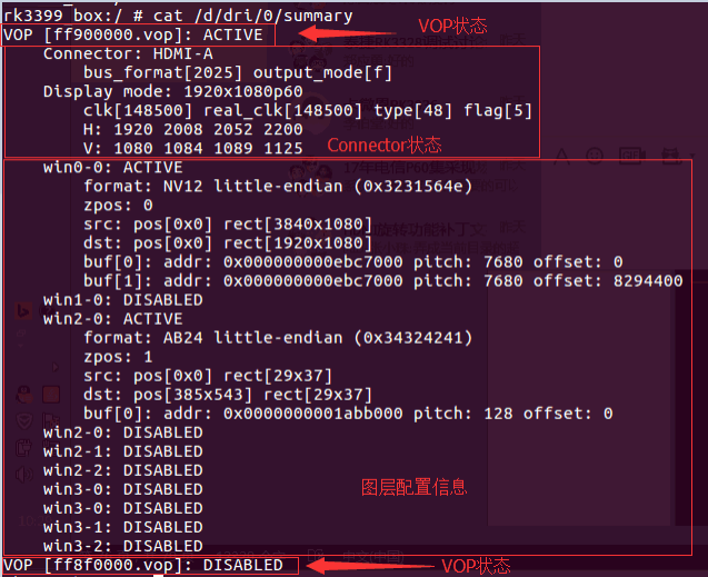
The above LOG is the output of the command when RK3399 is connected to HDMI, which can provide three types of information:
-
VOP status: VOPB is enabled, and VOPL is disabled.
-
Connector status corresponding to VOP: VOPB outputs signal to HDMI,
bus_format = 0x2025indicates YUV444 8bit,output_mode = 0x0findicates VOP outputs bus isROCKCHIP_OUT_MODE_AAAA, output 1920x1080P60. Commonbus_formatis defined in the kerneluapi/linux/media-bus-format.h:#define MEDIA_BUS_FMT_RGB888_1X24 0x100a //RGB888
#define MEDIA_BUS_FMT_RGB101010_1X30 0x1018 //RGB101010
#define MEDIA_BUS_FMT_YUV8_1X24 0x2025 //YUV444 8bit
#define MEDIA_BUS_FMT_YUV10_1X30 0x2016 //YUV444 10bit
#define MEDIA_BUS_FMT_UYYVYY8_0_5X24 0x2026 //YUV420 8bit
#define MEDIA_BUS_FMT_UYYVYY10_0_5X30 0x2027 //YUV420 10bitCommon
output_modeis defined in the kerneldrivers/gpu/drm/rockchip/rockchip_drm_vop.h:#define ROCKCHIP_OUT_MODE_P888 0
#define ROCKCHIP_OUT_MODE_P666 1
#define ROCKCHIP_OUT_MODE_P565 2
#define ROCKCHIP_OUT_MODE_S888 8
#define ROCKCHIP_OUT_MODE_S888_DUMMY 12
#define ROCKCHIP_OUT_MODE_YUV420 14
/* for use special outface */
#define ROCKCHIP_OUT_MODE_AAAA 15 -
Layer configuration information:
win0andwin2are enabled,win2buffer format is ARGB, buffer size is 29x37; target window is 29x37, window top-left corner coordinates (385,543)。Win0buffer format is NV12, size is 3840x2160; target window size is 1920x1080, top-left corner coordinates (0,0)。
2.3.2 View Connector Status
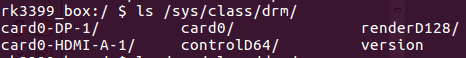
In the /sys/class/drm directory, you can see the various graphics cards registered by the driver. The following image is the DRM directory structure of the RK3399 BOX platform, where card0-HDMI-A-1 and card0-DP-1 indicate HDMI and DP respectively.
 Taking
 card0-HDMI-A-1 as an example, there are the following files under its directory:
Enabled: Enable statusStatus: Connection statusMode: Current output resolutionModes: List of resolutions supported by the connected deviceAudioformat: Supported audio formats of the connected deviceEdid: EDID of the connected device, which can be saved by the commandcat edid > /data/edid.bin.
2.3.3 View HDMI Working Status
If the following commit is included, you can view the HDMI working status:
commit eaca91814449199b1e6ad0b9fe0bba2215497c97
Author: Zheng Yang <zhengyang@rock-chips.com>
Date:   Mon Nov 27 16:56:21 2017 +0800
   drm: bridge: dw-hdmi: add hdmi status debugfs node
Use the following command to check the current HDMI output status:
cat /sys/kernel/debug/dw-hdmi/status
![]()
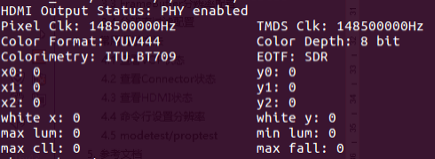
- HDMI Output Status indicates the current PHY status, and subsequent prints will only appear when the PHY is enabled.
- Pixel Clk: Indicates the current output pixel clock.
- TMDS Clk: Indicates the current HDMI character rate output.
- Color Format: Indicates the output color format, values RGB, YUV444, YUV422, YUV420.
- Color Depth: Indicates the output color depth, values 8bit, 10bit, 12bit, 16bit.
- Colorimetry: Indicates the color standard of the output, values ITU.BT601, ITU.BIT709, ITU.BT2020.
- EOTF: Indicates the HDR electro-optical conversion curve method of the output, with the following values:
EOTF meaning:
- Unsupported: HDMI does not support sending HDR information
- Not Defined: Undefined
- Off: Do not send HDR information
- SDR: Use SDR curve
- ST2084: Use ST2084 EOTF curve
- HLG: Use HLG EOTF curve
(x0,y0)、(x1,y1)、(x2,y2)、(white x,white y)、max lum、min lum、max cll、maxfall are static HDR descriptor information, which only exist when the EOTF value is SDR, ST2084, or HLG.
Executing the following command can view the HDMI controller registers:
cat /sys/kenrel/debug/dw-hdmi/ctrl
You can use commands to modify the registers, for example, to modify the 0x1000 register to 0xF8, enter the command:
echo 1000 f8 > /sys/kenrel/debug/dw-hdmi/ctrl
Modifying PHY registers is similar to modifying controller registers. For example, to modify the 0x06 register to 0x8002, enter the command:
echo 06 8002 > /sys/kenrel/debug/dw-hdmi/phy
2.3.4 View HDMI CEC Status
Execute the following command to view the HDMI CEC status:
cat /sys/kernel/debug/cec/cec0/status

The printed result is as follows:
configured: Indicates whether the cec adapter is configured, 1 for configured, 0 for not configured.configuring: Indicates whether the cec adapter is being configured, 1 for yes, 0 for configured or not started.phys_addr: Indicates the physical address of cec,f.f.f.fwhen the physical address is not obtained.number of LAs: Indicates the number of logical addresses bound to the cec device, mostly 1, a few are 2.LA mask: Indicates the current bound logical address, the specific value is0x0010when the right shift 4 bits is 1, indicating that the current logical address is 4, and the value is0x0800when the right shift 11 bits is 1, indicating that the current logical address is 11. If no logical address is bound, it is0x0000.has CEC follower: Indicates whether the received cec message is handed over to the upper user space for processing,in passthrough modeindicates that the kernel will not process the cec core message, but will report all to the upper user space for processing.pending transmits: Indicates how many cec messages are pending to be sent.
2.3.5 Force Enable/Disable HDMI
Force enable HDMI:
echo on > /sys/class/drm/card0-HDMI-A-1/status
Force disable HDMI:
echo off > /sys/class/drm/card0-HDMI-A-1/status
Restore hot-plug detection:
echo detect > /sys/class/drm/card0-HDMI-A-1/status
2.3.6 Command Line Set Resolution
In the Android system, you can use the command line to set the resolution by setting the property. In addition, when the user sets the resolution in the Android settings, the corresponding property value will also be set.
2.3.6.1 Android 7.x & Android 8.x Resolution Setting
| Property | Description |
|---|---|
| persist.sys.resolution.main | Set the primary screen resolution, the parameter is the timing of this resolution, see section 3.2.4. |
| persist.sys.resolution.aux | Set the secondary screen resolution, the parameter is the timing of this resolution, see section 3.2.4. |
| sys.display.timeline | Refresh the display timeline, increase by one each time a new resolution is set. |
Set the primary and secondary screen resolutions through persist.sys.resolution.main and persist.sys.resolution.aux, respectively. After each setting, update sys.display.timeline (increase by 1 each time) and then move the mouse or perform other UI update operations to make the new resolution take effect. Examples are as follows:
- Set 4k60:
   setprop persist.sys.resolution.main 3840x2160@60-3840-4016-4104-4400-2160-
  2168-2178-2250-5
setprop sys.display.timeline 1 - Set 1080p60:
setprop persist.sys.resolution.main 1920x1080@60-1920-2008-2052-2200-1080-
1084-1089-1125-5
setprop sys.display.timeline 2 - Set 720P60:
setprop persist.sys.resolution.main 1280x720@60.00-1390-1430-1650-725-730-
750-5
setprop sys.display.timeline 3 - Set 480P60:
setprop persist.sys.resolution.main 720x480@59.94-736-798-858-489-495-
525-a
setprop sys.display.timeline 4
2.3.6.2 Android 9.0 and Above Resolution Setting
The attributes used for resolution setting in the new and old Android 9.0 versions are different, and need to be distinguished according to the HWC version. The new Android 9.0 SDK and higher Android versions use the new attributes.
commit 6f772a162893dd0242b6644fa32166e1ac15b2c0
Author: libin <bin.li@rock-chips.com>
Date:   Wed May 12 15:00:05 2021 +0800
   DrmConnector : Add UpdateDisplayMode function
   In order to adapt to the three-screen version.
   The hwc switching resolution will be in accordance with
   the following priority:
     1.persist.vendor.resolution.<Connector-type>-<Connector-ID>
     2.persist.vendor.resolution.main(aux)
     3.baseparameter(if exist)
     4.use "Auto"
   Version: 1.1.137
   Signed-off-by: libin <bin.li@rock-chips.com>
   Change-Id: I73e216047ed5423929d7a091572d717c4ffdf50c
When the HWC code includes the above commit, the new attributes are used:
| Attribute | Description |
|---|---|
persist.vendor.resolution.HDMI-A-0 | Set the HDMI0 resolution, if setting HDMI1, it is HDMI-A-1, the parameter is the timing of this resolution, see section 3.2.4 |
vendor.display.timeline | Refresh the display timeline, increase by one each time a new resolution is set |
If the HWC does not contain the above attributes, the old attributes are used
| Attribute | Description |
|---|---|
persist.vendor.resolution.main | Set the primary screen resolution, the parameter is the timing of this resolution, see section 3.2.4 |
persist.vendor.resolution.aux | Set the secondary screen resolution, the parameter is the timing of this resolution, see section 3.2.4 |
vendor.display.timeline | Refresh the display timeline, increase by one each time a new resolution is set |
Set the primary and secondary screen resolutions through persist.vendor.resolution.main and persist.vendor.resolution.aux, respectively. After each setting, update vendor.display.timeline (increase by 1 each time) and then move the mouse or perform other UI update operations to make the new resolution take effect. Examples are as follows:
-
Set 4k60:
  setprop persist.vendor.resolution.main 3840x2160@60-3840-4016-4104-4400-2160-2168-2178-2250-5
setprop vendor.display.timeline 1 -
Set 1080p60:
setprop persist.vendor.resolution.main 1920x1080@60-1920-2008-2052-2200-1080-1084-1089-1125-5
setprop vendor.display.timeline 2 -
Set 720P60:
setprop persist.vendor.resolution.main 1280x720@60.00-1390-1430-1650-725-730-750-5
setprop vendor.display.timeline 3 -
Set 480P60:
setprop persist.vendor.resolution.main 720x480@59.94-736-798-858-489-495-525-a
setprop vendor.display.timeline 4
2.3.7 Command Line Set Color
In the Android system, you can use the command line to set the color by setting the property. In addition, when the user sets the color in the Android settings, the corresponding property value will also be set.
2.3.7.1 Android 7.x & Android 8.x Color Setting
| Property | Description |
|---|---|
| persist.sys.color.main | Set the primary screen color Parameter format: Color format-Color depthExample: RGB-8bitSupported color formats: - RGB - YCBCR444 - YCBCR422 - YCBCR420 Supported color depths: - 8bit (24bit) - 10bit |
| persist.sys.color.aux | Set the secondary screen color Parameters are the same as the primary screen |
| sys.display.timeline | Refresh the display timeline Each time a new resolution is set, increase by one |
Set the primary and secondary screen colors through persist.sys.color.main and persist.sys.color.aux, respectively. After each setting, update sys.display.timeline (increase by 1 each time) and then move the mouse or perform other UI update operations to make the new color take effect. Examples are as follows:
setprop persist.sys.color.main RGB-8bit
setprop sys.display.timeline 1
Set the output color to RGB, color depth 8bit (RGB 24bit).
2.3.7.2 Android 9.0 and Above Color Setting
Similar to the resolution setting, the attributes used for color setting in the new and old Android 9.0 versions are different, and need to be distinguished according to the HWC version. The new Android 9.0 SDK and higher Android versions use the new attributes.
commit 6f772a162893dd0242b6644fa32166e1ac15b2c0
Author: libin <bin.li@rock-chips.com>
Date:   Wed May 12 15:00:05 2021 +0800
   DrmConnector : Add UpdateDisplayMode function
   In order to adapt to the three-screen version.
   The hwc switching resolution will be in accordance with
   the following priority:
     1.persist.vendor.resolution.<Connector-type>-<Connector-ID>
     2.persist.vendor.resolution.main(aux)
     3.baseparameter(if exist)
     4.use "Auto"
   Version: 1.1.137
   Signed-off-by: libin <bin.li@rock-chips.com>
   Change-Id: I73e216047ed5423929d7a091572d717c4ffdf50c
When the HWC code includes the above commit, the new attributes are used:
| Attribute | Description |
|---|---|
persist.vendor.color.HDMI-A-0 | Set the HDMI0 color, if setting HDMI1, it is HDMI-A-1, parameter is Color format-Color depth. For example, to set the color to RGB, color depth 8bit (24bit), the parameter is RGB-8bit |
| Supported Color Formats | RGB, YCBCR444, YCBCR422, YCBCR420 |
| Supported Color Depths | 8bit, 10bit |
vendor.display.timeline | Refresh the display timeline, increase by one each time a new resolution is set |
If the HWC does not contain the above attributes, the old attributes are used:
| Attribute | Description |
|---|---|
persist.vendor.color.main | Set the primary screen color, parameter is Color format-Color depth. For example, to set the color to RGB, color depth 8bit (24bit), the parameter is RGB-8bit |
persist.vendor.color.aux | Set the secondary screen color, parameters are the same as the primary screen |
vendor.display.timeline | Refresh the display timeline, increase by one each time a new resolution is set |
Set the primary and secondary screen colors through persist.vendor.color.main and persist.vendor.color.aux, respectively. After each setting, update vendor.display.timeline (increase by 1 each time) and then move the mouse or perform other UI update operations to make the new color take effect. Examples are as follows:
setprop persist.vendor.color.main RGB-8bit
setprop vendor.display.timeline 1
Set the output color to RGB, color depth 8bit (RGB 24bit).
2.3.8 Set Overscan
Due to differences between TVs, the screen display may have issues such as the image exceeding the screen boundary or black edges around the image. In this case, overscan can be set to adjust the scaling size to correct these issues.
In the Android system, you can use the command line to set this property. In addition, users can also set overscan in the Android settings, and the corresponding property value will be set after the setting is completed.
2.3.8.1 Android 7.x & Android 8.x Overscan Setting
| Property | Description |
|---|---|
| persist.sys.overscan.main | Set the primary screen overscan, property format: overscan left,top,right,bottom left, top, right, bottom are the overscan values for the left, top, right, and bottom directions respectively, the minimum value is 1, the maximum value is defined by the property persist.sys.overscan.max, if persist.sys.overscan.max does not exist, the default is 100. |
| persist.sys.overscan.aux | Set the secondary screen overscan, parameters are the same as the primary screen. |
Example:
setprop persist.sys.overscan.main "overscan 70,70,70,70"
Set the overscan for all four directions to 70.
2.3.8.2 Android 9.0 and Above Overscan Setting
Refer to the description in section 3.3.6.2, select the attribute for setting according to the Android version.
New attribute:
| Attribute | Description |
|---|---|
| persist.vendor.overscan.HDMI-A-0 | Set the HDMI0 overscan, if setting HDMI1, it is HDMI-A-1, property format: overscan left,top,right,bottom. left, top, right, bottom are the overscan values for the left, top, right, and bottom directions respectively, the minimum value is 1, the maximum value is defined by the property persist.vendor.overscan.max, if persist.vendor.overscan.max does not exist, the default is 100. |
persist.vendor.overscan.main | Set the primary screen overscan, property format: overscan left,top,right,bottom. left, top, right, bottom are the overscan values for the left, top, right, and bottom directions respectively, the minimum value is 1, the maximum value is defined by the property persist.vendor.overscan.max, if persist.vendor.overscan.max does not exist, the default is 100. |
persist.vendor.overscan.aux | Set the secondary screen overscan, parameters are the same as the primary screen. |
Example:
setprop persist.vendor.overscan.main "overscan 70,70,70,70"
Set the overscan for all four directions to 70.
2.3.9 Set Brightness, Contrast, Saturation, and Hue
In the Android system, you can use the command line to set these parameters by setting the property. In addition, users can also set these parameters in the Android settings, and the corresponding property value will be set after the setting is completed.
2.3.9.1 Android 7.x & Android 8.x Brightness, Contrast, Saturation, and Hue Setting
| BCSH | Value Range | Description |
|---|---|---|
| Brightness | Integer, 0-100, default 50 | persist.sys.brightness.mainpersist.sys.brightness.aux |
| Contrast | Integer, 0-100, default 50 | persist.sys.contrast.mainpersist.sys.contrast.aux |
| Saturation | Integer, 0-100, default 50 | persist.sys.saturation.mainpersist.sys.saturation.aux |
| Hue | Integer, 0-100, default 50 | persist.sys.hue.mainpersist.sys.hue.aux |
| For example: |
setprop persist.sys.brightness.main 70
setprop vendor.display.timeline 1
Set the primary screen brightness to 70, and make the new brightness take effect by updating vendor.display.timeline.
2.3.9.2 Android 9.0 and Above Brightness, Contrast, Saturation, and Hue Setting
Refer to the description in section 3.3.6.2, select the attribute for setting according to the Android version. New attribute:
| Parameter | Value Range | Default Value | Attribute Name |
|---|---|---|---|
| Brightness | 0 - 100 | 50 | persist.vendor.brightness.HDMI-A-0 |
| Contrast | 0 - 100 | 50 | persist.vendor.contrast.HDMI-A-0 |
| Saturation | 0 - 100 | 50 | persist.vendor.saturation.HDMI-A-0 |
| Hue | 0 - 100 | 50 | persist.vendor.hue.HDMI-A-0 |
Old attribute:
| Parameter | Value Range | Default Value | Primary Screen Attribute Name | Secondary Screen Attribute Name |
|---|---|---|---|---|
| Brightness | 0 - 100 | 50 | persist.vendor.brightness.main | persist.vendor.brightness.aux |
| Contrast | 0 - 100 | 50 | persist.vendor.contrast.main | persist.vendor.contrast.aux |
| Saturation | 0 - 100 | 50 | persist.vendor.saturation.main | persist.vendor.saturation.aux |
| Hue | 0 - 100 | 50 | persist.vendor.hue.main | persist.vendor.hue.aux |
For example:
setprop persist.vendor.brightness.main 70
setprop sys.display.timeline 1
Set the primary screen brightness to 70, and make the new brightness take effect by updating vendor.display.timeline.
2.4 Common Troubleshooting Methods
2.4.1 No Signal or Unsupported Format or Unstable Image When Inserting or Switching Resolutions
- Check the current HDMI resolution, command see 3.3.2.
- Lower the HDMI resolution to see if the TV can display normally, command see 3.3.6.
- Replace with a good HDMI cable to see if the TV can display normally.
- If steps 2 and 3 can restore the image, it is generally related to the compatibility of the HDMI physical signal, check the hardware, test the HDMI signal for further analysis.
- If the HDMI signal is not up to standard, the configuration of HDMI PHY can be adjusted to adjust the signal, refer to 3.1.7.
2.4.2 No Signal or Unsupported Format When Playing Video
Check whether there is a DDR frequency scaling function for the video in the DTS of the kernel code, if any, set auto-freq-en = <0>; to turn off the automatic frequency scaling function.
 dmc: dmc {
               compatible = "rockchip,rk3328-dmc";
               devfreq-events = <&dfi>;
               clocks = <&cru SCLK_DDRCLK>;
               clock-names = "dmc_clk";
               operating-points-v2 = <&dmc_opp_table>;
               ddr_timing = <&ddr_timing>;
               upthreshold = <40>;
               downdifferential = <20>;
               system-status-freq = <
                       /*system status         freq(KHz)*/
                       SYS_STATUS_NORMAL       786000
                       SYS_STATUS_REBOOT       786000
                       SYS_STATUS_SUSPEND     786000
                       SYS_STATUS_VIDEO_1080P 786000
                       SYS_STATUS_VIDEO_4K     786000
                       SYS_STATUS_VIDEO_4K_10B 933000
                       SYS_STATUS_PERFORMANCE 933000
                       SYS_STATUS_BOOST       933000
               >;
               auto-min-freq = <786000>;
               auto-freq-en = <0>;
               #cooling-cells = <2>;
               status = "disabled";
2.4.3 Some TVs Show No Signal, Black Screen, or Mosaic
- Check the current HDMI resolution, command see 3.3.2.
- Lower the HDMI resolution to see if the TV can display normally, command see 3.3.6.
- Replace with a good HDMI cable to see if the TV can display normally.
- If steps 2 and 3 can restore the image, it is generally related to the compatibility of the HDMI physical signal, check the hardware, test the HDMI signal for further analysis.
- If the HDMI signal is not up to standard, the configuration of HDMI PHY can be adjusted to adjust the signal, refer to 3.1.7.
- If the HDMI signal is up to standard, you can try to modify the register values as shown below:
kernel\drivers\gpu\drm\bridge\synopsys\dw-hdmi.c
/* HDMI Initialization Step B.4 */
static void dw_hdmi_enable_video_path(struct dw_hdmi *hdmi)
{
 /* control period minimum duration */
 hdmi_writeb(hdmi, 12, HDMI_FC_CTRLDUR);
Gradually increase the value of HDMI_FC_CTRLDUR (maximum 223) in the code above and see if the display can return to normal.
2.4.4 Failed to Read EDID, How to Set Default Resolution
Commit 727e0fe68d8f422698f4e257cb7c04f90b8692c0
Author: xuhuicong xhc@rock-chips.com
Date:   Tue Sep 26 17:32:56 2017 +0800
drm/edid: output common tv resolution and hdmi mode if no read the correct edid
Change-Id: Ib7379340e8c1d59382553d21b60165fe5fb371e8
Signed-off-by: xuhuicong xhc@rock-chips.com
With the above commit, modify the value of def_modes, corresponding to the VIC value, as shown below. The 4 in the code below corresponds to the 720P60 resolution.
kernel\drivers\gpu\drm\bridge\synopsys\dw-hdmi.c
/* HDMI Initialization Step B.4 */
static void dw_hdmi_enable_video_path(struct dw_hdmi *hdmi)
{
 /* control period minimum duration */
 hdmi_writeb(hdmi, 12, HDMI_FC_CTRLDUR);
2.4.5 Force Output a Specified Resolution
When it is necessary to forcibly output a specific resolution regardless of EDID, the following commit should be included in the current code for RK3288/RK3368/RK3399/RK356X:
commit b318f175080ca98173d75fcf436beeee64092303
Author: Algea Cao <algea.cao@rock-chips.com>
Date:   Fri Nov 17 09:55:52 2023 +0800
   drm/bridge: synopsys: Support hdmi force output
   Support hdmi output specific resolution and color format
   regardless of whether hdmi is connected.
   Signed-off-by: Algea Cao <algea.cao@rock-chips.com>
   Change-Id: I228a74d128aa818166f589798897729473d97610
For RK3588/RK3576, check whether the following commit is included:
commit ed5631fa515a297b45cef5a1330b516f56e113dc
Author: Algea Cao <algea.cao@rock-chips.com>
Date:   Thu Dec 28 10:16:17 2023 +0800
   drm/bridge: dw-hdmi-qp: Support hdmi force output
   Support hdmi output specific resolution and color format
   regardless of whether hdmi is connected.
   Signed-off-by: Algea Cao <algea.cao@rock-chips.com>
   Change-Id: I3f18aeb04427846e06b6a4397a4c6df77bbbcab2
If the above commits are included, you can directly configure the desired resolution and color format in DTS:
&hdmi {
       status = "okay";
       force-output;
       force-bus-format = <MEDIA_BUS_FMT_RGB888_1X24>;
       force_timing {
               clock-frequency = <594000000>;
               hactive = <3840>;
               vactive = <2160>;
               hback-porch = <296>;
               hfront-porch = <176>;
               vback-porch = <72>;
               vfront-porch = <8>;
               hsync-len = <88>;
               vsync-len = <10>;
               hsync-active = <1>;
               vsync-active = <1>;
               de-active = <0>;
               pixelclk-active = <0>;
       };
};
force-output: Flag to force the output HDMI resolution.force-bus-format: Force output the specified color format.force_timing: Force output the specified resolution timing.
If the current code does not contain the above commits, please make the following modifications:
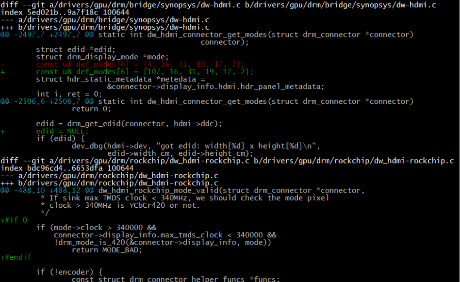
- Change the first value of the
def_modearray to the VIC corresponding to the desired resolution. edid = NULL;forcibly enters the process of reading EDID failure, regardless of whether the EDID is read, it is forcibly displayed according todef_modes.- If it is necessary to forcibly display 4K resolution, the code that restricts 4K resolution should be commented out as shown in the above image.
It should be noted that when forcibly outputting HDMI 2.0 (resolutions above 4K30) and higher resolutions, you need to confirm whether SINK needs to perform SCDC communication. If SCDC communication is required, the HDMI DDC function must be normal. And when forcing output, HDMI hot-plug is not supported.
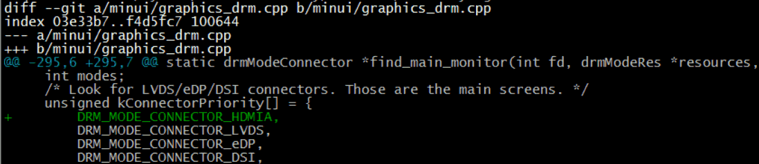
2.4.6 Recovery HDMI No Display
HDMI does not support dual display in Recovery, nor does it support hot-plug. If HDMI display is needed, the following modifications should be made in the code, and then HDMI should be plugged in and powered on.
2.4.7 settings Cannot Set HDMI Resolution
-
Please confirm whether the main and secondary screen configurations in 3.2.1 are correct, and whether the settings in 3.2.5 are correct.
-
Please confirm whether the attribute configuration in 3.3.6 is correct.
-
If it is Android 9.X and above, the RkOutputManager service needs to be enabled. The 3399 code needs to be updated to the following commit point.

-
Other 9.0 platforms need to apply corresponding patches. The patch is to execute
sourceandlunchrelated commands in the current project, and then executeget_build_var DEVICE_MANIFEST_FILE, the currently used manifest file will be printed, for example:
<hal format="hidl">
    <name>rockchip.hardware.outputmanager</name>
    <transport>hwbinder</transport>
    <version>1.0</version>
    <interface>
        <name>IRkOutputManager</name>
        <instance>default</instance>
    </interface>
</hal>
2.4.8 DDR Bandwidth Insufficient Issues
If there are screen flickering or green line flashing issues at 4K high resolution, check whether the following print appears in the kernel log:
[drm:vop_isr] ERROR POST_BUF_EMPTY irq err
If the above print appears, it is a DDR bandwidth insufficient issue, please refer to section 9.7 of "Rockchip_RK3399_Developer_Guide_Android7.1_Software_CN&EN.pdf" for processing.
2.4.9 4K UI Related Issues
- Is 4K UI really necessary?
- 4K UI occupies more system resources, and can only support up to about 4K25Hz, it is not recommended to use 4K UI. If you just want to play 4K videos or view 4K pictures, you may not need to configure 4K UI. The system's default video player and image browser can support it.
- How to configure 4K UI?
- Please refer to section 3.2.3, set the framebuffer resolution to 4K.
- If there is screen flickering after configuring 4K UI, please refer to section 3.4.10 for processing.
2.4.10 The 4K Resolution is Not in the HDMI Resolution List in settings
- Confirm whether the TV supports 4K resolution.
- Execute the following command to check whether the HDMI resolution list in the kernel includes 4K resolution.
cat /sys/class/drm/card0-HDMI-A-1/modes - If the 4K resolution is not included in the HDMI resolution list in the kernel, for dual VOP platforms (RK3288, RK3399), please confirm whether HDMI is bound to VOPB. Or the 4K-50/60Hz of this TV does not support YUV420, and the current platform does not support such a high resolution (please refer to the table in Chapter 1 for the highest resolution supported by the platform).
- If the HDMI resolution list in the kernel includes 4K resolution, but the resolution list in the settings does not include this resolution, please confirm whether this resolution is included in the whitelist (refer to section 3.2.4).
2.4.11 RK3588 The 8K Resolution is Not in the HDMI Resolution List in settings
- Confirm whether the TV settings select HDMI 2.1 mode or game mode, most 8K TVs need to be set manually, otherwise 8K resolution will not be available.
- Confirm whether the VOP ACLK is set to 800 MHz, see 3.1.5.
2.4.12 RK3588/RK3576 HDMI 8K/4K120 and Other Resolutions Flicker or Display Abnormally
- Confirm whether the HDMI cable used is an HDMI 2.1 cable. HDMI 2.1 resolutions must use HDMI 2.1 cables.
- Provide the HDMI schematic/PCB diagram for RK hardware review.
- Contact an external laboratory for SI testing or apply for RK hardware laboratory SI testing from the business.
2.4.13 Filling in the HDMI Certification Application Form
If you want to certify the device with HDMI, you will usually get a certification application form from the certification body, which is generally in the form of an excel sheet.
First, pay attention to the page labels at the bottom of the form, as in the following example:
![]()
The certification of various HDMI functions requires filling in the content of each page, and if the device does not support some functions, the corresponding page does not need to be filled in.
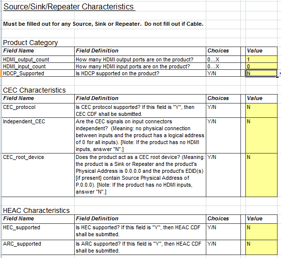
Common page descriptions are as follows:
- General: Generally, application forms have similar pages, and they must be filled in. Usually, it is about some basic information of the device HDMI. For example, how many HDMI IN ports does the device have, how many HDMI OUT ports, whether the device HDMI supports HDCP, CEC, and other functions. This page often determines whether the following pages need to be filled. For example, if HDMI_input_count is filled with 0, it means that the device does not support HDMI IN, and the Sink CDF page does not need to be filled.
- Source CDF: If the device has HDMI OUT ports (needs to fill in how many HDMI OUT ports are supported in the General page), this page needs to be filled, where you generally need to fill in which resolutions the HDMI OUT supports output, and which color formats are supported, etc.
- Sink CDF: If the device has HDMI IN ports, this page needs to be filled, where you generally need to fill in which resolutions the HDMI IN supports input, which color formats are supported, and EDID-related information, etc.
- Repeater CDF: This page needs to be filled if the device is used as an HDMI Repeater. Rockchip solutions generally do not include this product form.
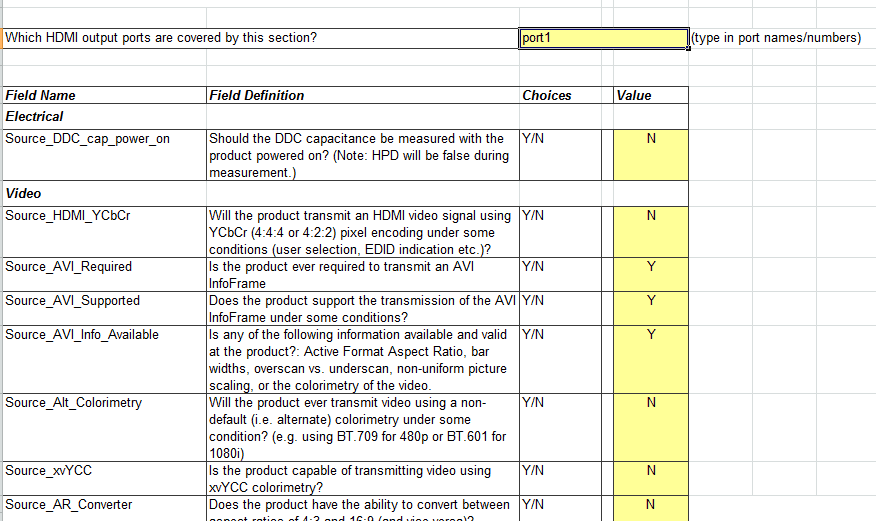
Each page generally contains several tables that need to be filled in, and the method of filling in is the same as that of ordinary excel tables. Taking the Video table under the Source CDF page as an example:
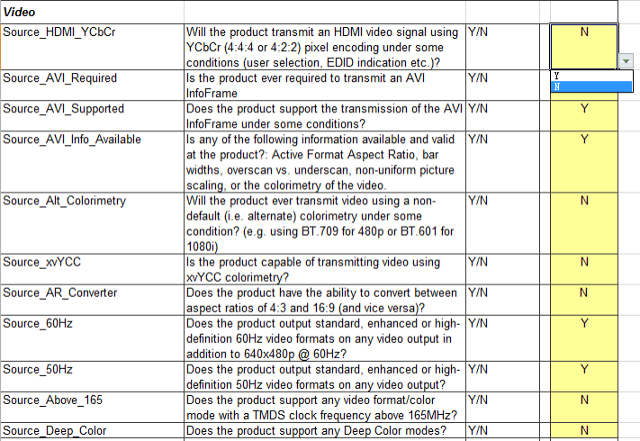
For the options in the table, describe them one by one according to the actual situation of the device. For example, the Source_HDMI_YCbCr item in the above figure, the first column is the item name, the second column is the item description, the third column is the optional value, and the fourth column is the value that the applicant needs to fill in. According to the description, this item indicates whether HDMI supports output YCbCr color format. If this function is supported, select Y in the drop-down list on the right, otherwise select N.
Since there are many items in the form, they will not be explained one by one here. If you have any questions about filling in any items, please raise them on redmine.