
SPI
Chip Names and Kernel Versions
| Chip Name | Kernel Version |
|---|---|
| All chips using Linux 4.4 | Linux 4.4 |
| All chips using Linux 4.19 and above | Linux 4.19 and above |
Introduction
Overview
This document introduces the Linux SPI driver principles and basic debugging methods.
Target Audience
This document is primarily intended for:
- Technical Support Engineers
- Software Development Engineers
1. Rockchip SPI Features
SPI (serial peripheral interface), the following are features supported by the Linux 4.4 SPI driver:
- Default Motorola SPI protocol
- Support for 8-bit and 16-bit
- Software programmable clock frequency
- Support for 4 SPI transfer modes configuration
- Each SPI controller supports one to two chip selects
- Support for SPI slave mode, with SPI_CS0N only as CS input pin:
- No switching to GPIO function allowed during transfer
- CS1N replacement not supported In addition to the above support, Linux 4.19 adds the following features:
- Framework supports both slave and master modes
1.1 SPI Interface Rates
| Chip Name | Master Mode Max Interface Rate | Slave Mode Max Interface Rate |
|---|---|---|
| RK3506 | 50MHz | 50MHz |
| RV1106B/RV1103B | 50MHz | 33MHz |
| RK3576 | 50MHz | 33MHz |
| RK3562 | 50MHz | 33MHz |
| RK3528 | 50MHz | 33MHz |
| RV1106/RV1103 | 50MHz | 33MHz |
| RK3588 | 50MHz | 33MHz |
| RV1126/RV1109 | 50MHz | 16MHz |
| RK3568 | 50MHz | 33MHz |
| RK1808 | 50MHz | 16MHz |
| RK3308 | 50MHz | 16MHz |
| Other platforms | 50MHz | 16MHz |
Notes:
- The maximum interface rates are theoretical rates, actual rates depend on PCB trace quality and should be verified through testing.
- Some platforms cannot accurately divide down to the upper limit value due to PLL strategy limitations, actual maximum is determined by the maximum division value.
2. Kernel Software
2.1 Code Paths
drivers/spi/spi.c: SPI driver frameworkdrivers/spi/spi-rockchip.c: RK SPI interface implementationsdrivers/spi/spi-rockchip-slave.c: RK SPI slave interface implementationsdrivers/spi/spidev.c: Create SPI device nodes for user space usagedrivers/spi/spi-rockchip-test.c: SPI test driver, needs to be manually added to MakefileDocumentation/spi/spidev_test.c: User space SPI test tools
2.2 SPI Device Configuration — RK Chip as Master
Kernel Configuration
Device Drivers --->
    [*] SPI support --->
        <*>   Rockchip SPI controller driver
DTS Node Configuration
&spi1 {
    status = "okay";
    // assigned-clocks = <CLK_SPI1>; // No need to configure by default, check CLK_SPIn from corresponding soc dtsi
    // assigned-clock-rates = <200000000>; // No need to configure by default, SPI device working clock value
    // dma-names; // No need to configure by default, disable DMA support, only support IRQ transfer
    // rockchip,poll-only; // No need to configure by default, force CPU transfer when enabled, only supported in master mode
    // rx-sample-delay-ns = <10>; // No need to configure by default, read sampling delay, see "Common Issues" "Delay Sampling Clock Configuration" section for details
    // rockchip,autosuspend-delay-ms = <500>; // No need to configure by default, Runtime PM autosuspend delay, see "SPI Transfer Rate and CPU Load Optimization"
    // rockchip,rt; // No need to configure by default, puts spi data transfer process in SCHED_FIFO class with priority 50
    spi_test@10 {
        compatible = "rockchip,spi_test_bus1_cs0"; // Name corresponding to driver
        reg = <0>; // Chip select 0 or 1
        spi-cpha; // Set CPHA = 1, default is 0 if not configured
        spi-cpol; // Set CPOL = 1, default is 0 if not configured
        spi-lsb-first; // Transfer LSB first
        spi-max-frequency = <24000000>; // SPI clock output frequency, not exceeding 50M
        status = "okay"; // Enable device node
    };
};
Configuration notes for spiclk assigned-clock-rates and spi-max-frequency:
spi-max-frequencyis the SPI output clock, derived from the SPI working clockspiclk assigned-clock-ratesthrough internal division. Due to minimum internal division of 2, the relationship isspiclk assigned-clock-rates >= 2 * spi-max-frequency- For example, if 50MHz SPI IO rate is needed, consider configuring (remember internal division must be even)
spi_clk assigned-clock-rates = <100000000>,spi-max-frequency = <50000000>, meaning 100MHz working clock (PLL divided to closest value not exceeding 100MHz), then internal division by 2 for final IO close to 50MHz spiclk assigned-clock-ratesshould not be lower than 24M to avoid potential issues
2.3 SPI Device Configuration — RK Chip as Slave
Key Patches
It is recommended to use the SPI slave source code spi-rockchip-slave.c. Due to SDK version issues, please confirm whether the SDK has the following patch:
commit 10cbf3c2c93fca6e5ec6c99b5bdb319ca0494d45
Author: Jon Lin <jon.lin@rock-chips.com>
Date:   Tue Nov 21 10:58:57 2023 +0800
    spi: rockchip-slave: Add code
    1. Implement one msg mechanism
    2. Support SRAM extension by dts rockchip,sram property
    Change-Id: I0fccc5d4347294488b5382ad3ba5ae72b35610f2
    Signed-Off-By: Jon Lin <jon.lin@rock-chips.com>
Note:
- If the patch is not available, customers can directly obtain it from Redmine -> FAE Project -> Documentation -> Development Configuration Document -> SPI path.
Kernel Configuration
Device Drivers --->
    [*] SPI support --->
        [*]   SPI slave protocol handlers
        [*]   Rockchip SPI Slave controller driver
DTS Node Configuration
&spi1 {
    compatible = "rockchip,spi-slave"; // Prefer to use dedicated SPI slave driver
    status = "okay";
    // ready-gpios = <&gpio1 RK_PD2 GPIO_ACTIVE_LOW>; // Recommended configuration, signal for SPI slave to complete transmission, refer to "Kernel SPI Slave Software" section for details
    // rockchip,cs-inactive-disable; // No need to configure by default, when SPI master timing tod_cs (Clk Rise To CS Rise Time) exceeds multiple io clock cycles, enable this to mask CS release detection
    slave { // According to framework requirements, SPI slave sub-node naming must start with "slave"
        compatible = "rockchip,spi_test_bus1_cs0";
        reg = <0>; // Chip select only supports 0
        spi-cpha; // Set CPHA = 1, default is 0 if not configured
        spi-cpol; // Set CPOL = 1, default is 0 if not configured
        spi-lsb-first; // Transfer LSB first
        status = "okay"; // Enable device node
    };
};
Note:
- RK SPI defaults to enable DMA transfer, it is not recommended to disable DMA transfer in slave mode. When a transmission exceeds the controller's cache size, the software will configure DMA transfer to avoid delayed interrupt response.
2.4 SPI Slave Considerations
2.4.1 Recommended Performance Settings
When the master rate exceeds a certain frequency, it is recommended to set the performance mode during the transmission process to avoid controller cache overflow caused by DRAM frequency switching:
bits_per_word = 8bits,master io rate exceeds 5MHzbits_per_word = 16bits,master io rate exceeds 10MHz
Reference Code:
diff --git a/drivers/spi/spi-rockchip-test.c b/drivers/spi/spi-rockchip-test.c
index 544d6038919a..c1037153ff86 100644
--- a/drivers/spi/spi-rockchip-test.c
+++ b/drivers/spi/spi-rockchip-test.c
@@ -36,6 +36,8 @@
 #include <linux/platform_data/spi-rockchip.h>
 #include <linux/uaccess.h>
 #include <linux/syscalls.h>
+#include <soc/rockchip/rockchip-system-status.h>
+#include <dt-bindings/soc/rockchip-system-status.h>
 #define MAX_SPI_DEV_NUM 10
 #define SPI_MAX_SPEED_HZ       12000000
@@ -242,8 +244,10 @@ static ssize_t spi_test_write(struct file *file,
                }
                start_time = ktime_get();
+               rockchip_set_system_status(SYS_STATUS_PERFORMANCE);
                for (i = 0; i < times; i++)
                        spi_read_slt(id, rxbuf, size);
+               rockchip_clear_system_status(SYS_STATUS_PERFORMANCE);
                end_time = ktime_get();
                cost_time = ktime_sub(end_time, start_time);
                us = ktime_to_us(cost_time);
Note:
-
It is recommended that all slave mode transmission behaviors operate in performance mode.
-
The set/clear performance interface has some time overhead, so it is recommended to be set by the upper business layer to avoid frequent calls.
-
If the cache overflows and the slave cannot complete the DMA transfer, it will be blocked and unable to exit. By printing the SPI->SPI_RISR register, you can check whether a cache overflow has occurred.
2.4.2 Recommended 16bits Width Setting
Maximize the use of slave FIFO capacity, with burst size at least 2, to accelerate the DMA transfer rate on the slave side and avoid FIFO overflow due to slow data movement.
2.4.3 Other Considerations
SPI Slave Testing Notes: When SPI acts as a slave, start the slave read first, then start the master write, otherwise, the slave may not finish reading before the master has already written.
For slave write and master read, the slave write must be started first, because only after the master sends the clock, the slave will work, and the master will immediately send or receive data.
For example:Based on the third chapter:
- First slave:
echo write 0 1 16 > /dev/spi_misc_test - Then master:
echo read 0 1 16 > /dev/spi_misc_test
2.5 SPI Device Driver Introduction
Device Driver Registration:
#include <linux/init.h>
#include <linux/module.h>
#include <linux/platform_device.h>
#include <linux/of.h>
#include <linux/spi/spi.h>
static int spi_test_probe(struct spi_device *spi)
{
    int ret;
    if(!spi)
        return -ENOMEM;
    spi->bits_per_word= 8;
    ret= spi_setup(spi);
    if(ret < 0) {
        dev_err(&spi->dev,"ERR: fail to setup spi\n");
        return-1;
   }
    return ret;
}
static int spi_test_remove(struct spi_device *spi)
{
    printk("%s\n",__func__);
    return 0;
}
static const struct of_device_id spi_test_dt_match[]= {
   {.compatible = "rockchip,spi_test_bus1_cs0", },
   {.compatible = "rockchip,spi_test_bus1_cs1", },
   {},
};
MODULE_DEVICE_TABLE(of, spi_test_dt_match);
static struct spi_driver spi_test_driver = {
   .driver = {
       .name  = "spi_test",
       .owner = THIS_MODULE,
       .of_match_table = of_match_ptr(spi_test_dt_match),
   },
   .probe = spi_test_probe,
   .remove = spi_test_remove,
};
static int __init spi_test_init(void)
{
    int ret = 0;
    ret = spi_register_driver(&spi_test_driver);
    return ret;
}
module_init(spi_test_init);
static void __exit spi_test_exit(void)
{
    return spi_unregister_driver(&spi_test_driver);
}
module_exit(spi_test_exit);
For SPI read and write operations, please refer to include/linux/spi/spi.h, here are a few simple ones
static inline int
spi_write(struct spi_device *spi,const void *buf, size_t len)
static inline int
spi_read(struct spi_device *spi,void *buf, size_t len)
static inline int
spi_write_and_read(structspi_device *spi, const void *tx_buf, void *rx_buf,
size_t len)
2.6 User Mode SPI Device Configuration
User mode SPI device refers to direct operation of the SPI interface from user space, making it convenient for many SPI peripheral drivers to run in user space without modifying the kernel, facilitating driver porting and development.
Kernel Configuration
Device Drivers --->
    [*] SPI support --->
        [*]   User mode SPI device driver support
DTS Configuration
&spi0 {
    status = "okay";
    max-freq = <50000000>;
    spi_test@0 {
        compatible = "rockchip,spidev";
        reg = <0>;
        spi-max-frequency = <5000000>;
    };
};
Usage Notes:
- After the driver device is successfully loaded and registered, a device with a name similar to
/dev/spidev1.1will appear. - For device node read/write operation examples, please refer to:
- Kernel 4.4:
Documentation/spi/spidev_test.c - Kernel 4.19 and later:
tools/spi/spidev_test.c
- Kernel 4.4:
- After kernel project compilation, enter the corresponding path and input the following command to directly compile the standard SPI app program:
make CROSS_COMPILE=~/path-to-toolchain/gcc-xxxxx-toolchain/bin/xxxx-linux-gnu-
Supports configuration as an SPI slave device, refer to "SPI Device Configuration — RK Chip as Slave End", where the DTS configuration sub node should remain as "rockchip,spidev".
2.7 cs-gpios Support
Users can implement GPIO-simulated CS to extend SPI chip select signals through the cs-gpios property of spi-bus. Detailed information about the cs-gpios property can be found in the kernel documentation Documentation/devicetree/bindings/spi/spi-bus.txt.
2.7.1 Linux 4.4 Configuration
This support requires multiple patches. Please contact RK engineers to obtain the corresponding patches.
2.7.2 Linux 4.19 and Later Kernel Configuration
Example using SPI1 setting GPIO0_C4 as spi1_cs2n extension pin
Set cs-gpio pins and reference them in SPI node:
diff --git a/arch/arm/boot/dts/rv1126-evb-v10.dtsi b/arch/arm/boot/dts/rv1126-
evb-v10.dtsi
index 144e9edf1831..c17ac362289e 100644
--- a/arch/arm/boot/dts/rv1126-evb-v10.dtsi
+++ b/arch/arm/boot/dts/rv1126-evb-v10.dtsi
&pinctrl {
       ...
+
+       spi1 {
+               spi1_cs0n: spi1-cs1n {
+                       rockchip,pins =
+                               <0 RK_PC2 RK_FUNC_GPIO
&pcfg_pull_up_drv_level_0>;
+               };
+               spi1_cs1n: spi1-cs1n {
+                       rockchip,pins =
+                               <0 RK_PC3 RK_FUNC_GPIO
&pcfg_pull_up_drv_level_0>;
+               };
+               spi1_cs2n: spi1-cs2n {
+                       rockchip,pins =
+                               <0 RK_PC4 RK_FUNC_GPIO
&pcfg_pull_up_drv_level_0>;
+               };
+       };
};
diff --git a/arch/arm/boot/dts/rv1126.dtsi b/arch/arm/boot/dts/rv1126.dtsi
index 351bc668ea42..986a85f13832 100644
--- a/arch/arm/boot/dts/rv1126.dtsi
+++ b/arch/arm/boot/dts/rv1126.dtsi
spi1: spi@ff5b0000 {
       compatible = "rockchip,rv1126-spi", "rockchip,rk3066-spi";
       reg = <0xff5b0000 0x1000>;
       interrupts = <GIC_SPI 11 IRQ_TYPE_LEVEL_HIGH>;
       #address-cells = <1>;
       #size-cells = <0>;
       clocks = <&cru CLK_SPI1>, <&cru PCLK_SPI1>;
       clock-names = "spiclk", "apb_pclk";
       dmas = <&dmac 3>, <&dmac 2>;
       dma-names = "tx", "rx";
       pinctrl-names = "default", "high_speed";
-       pinctrl-0 = <&spi1m0_clk &spi1m0_cs0n &spi1m0_cs1n &spi1m0_miso
&spi1m0_mosi>;
-       pinctrl-1 = <&spi1m0_clk_hs &spi1m0_cs0n &spi1m0_cs1n &spi1m0_miso_hs
&spi1m0_mosi_hs>;
+       pinctrl-0 = <&spi1m0_clk &spi1_cs0n &spi1_cs1n &spi1_cs2n &spi1m0_miso
&spi1m0_mosi>;
+       pinctrl-1 = <&spi1m0_clk_hs &spi1_cs0n &spi1_cs1n &spi1_cs2n
&spi1m0_miso_hs &spi1m0_mosi_hs>;
       status = "disabled";
};
Redefine CS pins in SPI node:
+&spi1 {
+       status = "okay";
+       max-freq = <48000000>;
+       cs-gpios = <&gpio0 RK_PC2 GPIO_ACTIVE_LOW>, <&gpio0 RK_PC3
GPIO_ACTIVE_LOW>, <&gpio0 RK_PC4 GPIO_ACTIVE_LOW>;
       spi_test@0 {
               compatible = "rockchip,spi_test_bus1_cs0";
...
+       spi_test@2 {
+               compatible = "rockchip,spi_test_bus1_cs2";
+               id = <2>;
+               reg = <0x2>;
+               spi-cpha;
+               spi-cpol;
+               spi-lsb-first;
+               spi-max-frequency = <16000000>;
+       };
};
Notes:
- If expanding
cs-gpios, all CS pins must be converted to GPIO function and supported throughcs-gpiosextension.
3. Kernel Test Software
3.1 Code Path
drivers/spi/spi-rockchip-test.c
3.2 SPI Test Device Configuration
Kernel Patch
Need to manually add to compilation:
drivers/spi/Makefile
+obj-y                                 += spi-rockchip-test.o
DTS Configuration
&spi0 {
   status = "okay";
   spi_test@0 {
       compatible = "rockchip,spi_test_bus0_cs0";
       id = <0>;                                       // This property in spi-rockchip-test.c is used to distinguish different SPI slave devices
       reg = <0>;                                     // chip select 0:cs0 1:cs1
       spi-max-frequency = <24000000>;                // spi clock output frequency, not exceeding 50M
   };
   spi_test@1 {
       compatible = "rockchip,spi_test_bus0_cs1";
       id = <1>;
       reg = <1>;
       spi-max-frequency = <24000000>;
   };
};
Driver Log
[   0.457137] rockchip_spi_test_probe:name=spi_test_bus0_cs0,bus_num=0,cs=0,mode=11,speed=16000000
[   0.457308] rockchip_spi_test_probe:name=spi_test_bus0_cs1,bus_num=0,cs=1,mode=11,speed=16000000
3.3 Test Commands
echo write 0 10 255 > /dev/spi_misc_test
echo write 0 10 255 init.rc > /dev/spi_misc_test
echo read 0 10 255 > /dev/spi_misc_test
echo loop 0 10 255 > /dev/spi_misc_test
echo setspeed 0 1000000 > /dev/spi_misc_test
echo type id loop_count transfer_length > /dev/spi_misc_test
echo setspeed id frequency(Hz) > /dev/spi_misc_test
You can modify the test cases as needed.
4. Kernel SPI Slave Software
4.1 Introduction
Background:
- SPI master-slave communication usually follows specific protocols, such as SPI Nor being compatible with JEDEC SDFP protocol. As a device-side transmission, RK SPI slave should also follow specific protocols. Since there is no standard protocol format, RK provides customized transmission protocols and device drivers for customer reference.
- Linux SPI slave driver framework limitations:
- Uses transmission queues; although awakened queue threads have high priority, scheduling effects mean real-time performance cannot be fully guaranteed.
- RK SPI slave mode limitations:
- Each transmission requires re-initiating SPI controller configuration. Therefore, to ensure SPI master can detect when RK SPI slave completes transmission configuration and initiate data transfer, RK SPI slave needs to add a side-band signal as a ready status bit.
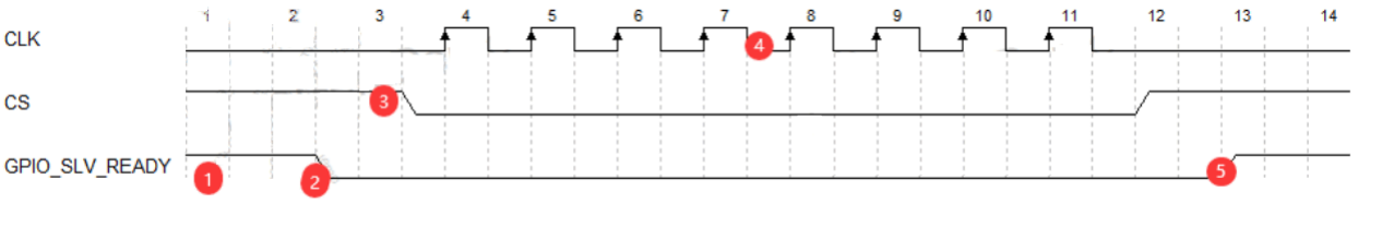
Transmission Protocol:
-
RK SPI slave transmission protocol:
- RK SPI slave transmission requires specifying
ready-gpiosto notify SPI master, basic flow:- Slave initiates
spi_sync - Slave ready, enables GPIO_SLV_READY signal
- Master confirms slave ready then initiates transfer
- Slave receives sufficient clock from master to complete transfer
- Slave idle, releases GPIO_SLV_READY signal
- Slave initiates
- Defines two packet types:
- ctrl packet: 2B cmd, 2B addr (RK slave-defined application buffer offset address), 4B data (typically used to specify subsequent data packet transfer length)
- data packet
- Defines two transfer types:
- ctrl transfer, contains only 1 ctrl packet
- data transfer, contains 1 ctrl packet and 1 data packet in two SPI transfers
spidev_rkslvsupports application buffer of lengthSPI_OBJ_APP_RAM_SIZEfor caching transfer data, SPI master-initiated data transfer 1 ctrl packet 2B addr points to this cache offset address.
- RK SPI slave transmission requires specifying
Device Driver:
Key Patches
commit d2fef34977c1a7aab3837d29ac8dc3b5378a2754 (HEAD -> develop-4.19)
Author: Jon Lin <jon.lin@rock-chips.com>
Date:   Wed Dec 20 12:02:14 2023 +0800
    spi: spidev_rkslv: Support dynamic adjustment of system performance
    If the DRAM frequency conversion jitters during the transmission process,
    it will cause the DMA to be unable to transport SPI FIFO data in a timely
    manner, resulting in FIFO overflow/underflow.
    Clear performance status for short cmd packet and Set the performance
    status for data packet.
    Change-Id: I65532ba309677a8d98c8277875a3bd358ca44e44
    Signed-off-by: Jon Lin <jon.lin@rock-chips.com>
Note:
- Due to SDK version issues, it is recommended to first confirm whether the SDK has the following patch. If not, customers can directly obtain it from Redmine -> FAE Project -> Documentation -> Development Configuration Document -> SPI path.
Driver Source Code:
drivers/spi/spidev-rkslv.c:drivers/spi/spidev-rkmst.c:
Source code introduction:
drivers/spi/spidev-rkslv.c:
static int spidev_rkslv_ctrl_receiver_thread(void *p)                   //Establish line
程,线程内重复发起传输
{
    while (1)
        spidev_rkslv_xfer(spidev);
}
static int spidev_rkslv_xfer(struct spidev_rkslv_data *spidev)          //Transmission input port
{
    spidev_slv_read(spidev, spidev->ctrlbuf, SPI_OBJ_CTRL_MSG_SIZE);    //1 ctrl
packet,获取并解析传输类型
    switch (ctrl->cmd) {                                                //1 data
packet,根据传输类型,定义 data packet 并完成收发
    case SPI_OBJ_CTRL_CMD_INIT:
        /* to-do */
    case SPI_OBJ_CTRL_CMD_READ:
        /* to-do */
    case SPI_OBJ_CTRL_CMD_WRITE:
        /* to-do */
    case SPI_OBJ_CTRL_CMD_DUPLEX:
        /* to-do */
   }
}
static const struct file_operations spidev_rkslv_misc_fops = {}          //注册 misc device 测试接口
drivers/spi/spidev-rkmst.c:
static int spidev_rkmst_xfer(struct spidev_rkmst_data *spidev, void *tx, void
*rx, u16 addr, u32 len)  //Transmission input port
{
    spidev_rkmst_ctrl(spidev, cmd, addr, len);                           //1 ctrl
packet,定义传输类型
    switch (cmd) {                                                       //1 data
packet,根据传输类型,定义 data packet 并完成收发
    case SPI_OBJ_CTRL_CMD_READ:
        /* to-do */
    case SPI_OBJ_CTRL_CMD_WRITE:
        /* to-do */
    case SPI_OBJ_CTRL_CMD_DUPLEX:
        /* to-do */
   }
}
static const struct file_operations spidev_rkmst_misc_fops = {}          //注册 misc device 测试接口
Business Implementation:
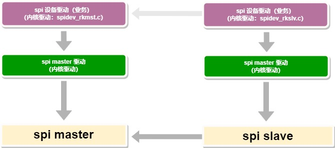
- The purpose of providing "Kernel SPI slave software" is to offer a reference for protocols and device drivers. Ultimately, customers should define their product requirements on the slave side's application buffer to实现业务.
4.2 SPI Slave Test Device Configuration
defconfig Configuration
CONFIG_SPI_SLAVE_ROCKCHIP_OBJ=y
RK SPI slave 端 dts 参考配置
&spi1 {
    compatible = "rockchip,spi-slave";
    status = "okay";
    rockchip,cs-inactive-disable; // RK 内部互联使用 RK Linux SPI master 驱动,tod_cs 较长
    ready-gpios = <&gpio1 RK_PD3 GPIO_ACTIVE_LOW>; // 请设置为实际所用 GPIO
    slave {
        compatible = "rockchip,spi-obj-slave";
        reg = <0x0>;
        spi-cpha;
        spi-cpol;
        spi-lsb-first;
        spi-max-frequency = <50000000>;
    };
};
RK SPI master 端 dts 参��考配置
&spi0 {
    status = "okay";
    spi_test@00 {
        compatible = "rockchip,spi-obj-master";
        reg = <0x0>;
        spi-cpha;
        spi-cpol;
        spi-lsb-first;
        spi-max-frequency = <16000000>;
        ready-gpios = <&gpio1 RK_PD2 GPIO_ACTIVE_LOW>; // 请设置为实际所用 GPIO
    };
};
4.3 Test Commands
SPI Master Single Packet Data Transfer Test
echo cmd addr length > /dev/spidev_rkmst_misc
Description:
cmd: Supportsread/write/duplexaddr: Offset in the slave application buffer, unit in Bytes, only supports decimal inputlength: Data packet length, unit in Bytes, only supports decimal input
For example:
echo write 128 128 > /dev/spidev_rkmst_misc
echo read 128 128 > /dev/spidev_rkmst_misc
echo duplex 128 128 > /dev/spidev_rkmst_misc
SPI Master Automated Testing
echo autotest length loops compare > /dev/spidev_rkmst_misc
Description:
autotest: Fixed input, first tests full-duplex data transfer, then tests read/write data transfer, and outputs rate results- Test uses offset address 0 in slave application buffer by default
length: Data packet length, unit in Bytes, only supports decimal inputloops: Sets the number of stress test cyclescompare: 1 - Enable data verification; 0 - Disable data verification (supports specific scenarios, like continuous data output for signal testing)
For example:
echo autotest 1024 64 1 > /dev/spidev_rkmst_misc
SPI Slave Testing
echo appmem 0 256 > ./dev/spidev_rkslv_misc      # Print application buffer data
echo verbose 1 > ./dev/spidev_rkslv_misc         # Enable debug log for transfer process, echo verbose 0 to disable printing
5. Common Issues
5.1 No SPI Signal
- Confirm the driver is running before debugging
- Ensure the IOMUX configuration of the 4 SPI pins is correct
- For TX transmission, verify TX pin has normal waveform, CLK has normal CLOCK signal, and CS signal is pulled low
- If clk frequency is high, consider increasing drive strength to improve signal
- To check if SPI DMA is enabled, DMA is successfully enabled if the following keywords are not present in serial output:
[   0.457137] Failed to request TX DMA channel
[   0.457237] Failed to request RX DMA channel
5.2 How to Write SPI Application Code
- Please select an appropriate target function interface before writing the driver.
Custom SPI Device Driver
- Reference: Write according to "SPI Device Driver Introduction", example:
drivers/spi/spi-rockchip-test.c.
Application
- Reference: See the "User mode SPI device configuration" section.
5.3 Delay Sampling Clock Configuration Scheme
For scenarios with high SPI IO rates, the normal SPI mode may still not match the output delay of external devices. RK SPI master read may fail to capture valid data, so the SPI rsd logic needs to be enabled to delay the sampling clock.
RK SPI rsd (read sample delay) Control Logic Features
- Configurable values: 0, 1, 2, 3
- Delay unit: 1 spi_clk cycle, i.e., the controller's working clock. See the "SPI Device Configuration" section for details.
- The actual delay of
rx-sample-delayis determined by the closest valid rsd value to the DTS setting. For example, with spi_clk at 200MHz (period 5ns):- The actual configurable rsd delays are 0, 5ns, 10ns, 15ns.
- If
rx-sample-delayis set to 12ns, the closest valid value is 10ns, so the final delay is 10ns.
5.4 SPI Transfer Mode Description
Default Transfer Mode
- Master mode supports IRQ, DMA and CPU transfer, Slave mode supports IRQ and DMA transfer, both default to IRQ/DMA combined transfer mode:
- When transfer length < fifo depth, use IRQ transfer, default fifo depth is 64 for SOCs using kernel 4.19 and above
- When transfer length >= fifo depth, use DMA transfer
Transfer Mode Modification
- Master mode supports:
- Default IRQ/DMA combined transfer mode
- Refer to "Disable DMA support, only support IRQ transfer" description to disable DMA and only support IRQ transfer
- Refer to "rockchip,poll-only" description to only support CPU transfer
- Slave mode does not support transfer mode modification.