

Clock
| Chip Name | Kernel Version |
|---|---|
| RK303X | LINUX4.4 & 4.19 & 5.10 |
| RK312X | LINUX4.4 & 4.19 & 5.10 |
| RK322X | LINUX4.4 & 4.19 & 5.10 |
| RK3288X | LINUX4.4 & 4.19 & 5.10 |
| RK3328 | LINUX4.4 & 4.19 & 5.10 |
| RK3368 | LINUX4.4 & 4.19 & 5.10 |
| RK3399 | LINUX4.4 & 4.19 & 5.10 |
| RV1108 | LINUX4.4 & 4.19 & 5.10 |
| PX30 | LINUX4.4 & 4.19 & 5.10 |
| RV1126 | LINUX4.19 & 5.10 |
| RK356X | LINUX4.19 & 5.10 |
| RK3588 | LINUX5.10 |
| RK3576 | LINUX6.1 |
| RV1103B | LINUX5.10 |
| RK3506 | LINUX6.1 |
Preface
This document mainly introduces the RK platform clock subsystem framework and configuration.
Target Audience
This document (this guide) is mainly intended for the following engineers:
- Technical support engineers
- Software development engineers
1. Solution Overview
1.1 Overview
This chapter mainly describes important concepts related to the clock subsystem, clock schemes, overall process, and code structure.
1.2 Important Concepts
Clock Subsystem
The clock here refers to the tree framework that provides clocks to various SOC components, not the time used by the kernel. Like other modules, CLOCK also has a framework for adapting to different platforms. Above the adaptation layer is customer code and interfaces, that is, drivers for each module (such as peripherals that require clock signals, USB, etc.). Below the adaptation layer are the specific SOC-level clock operation details.
Clock Tree Structure
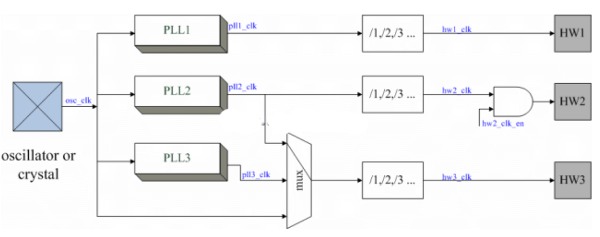
Mainstream processor platforms that can run LINUX all have very complex CLOCK TREEs. If you look at the CLOCK-related chapters in any processor's SPEC, there will definitely be a huge and complex tree diagram, which consists of CLOCK-related devices and the CLOCKs output by these devices.
Related Devices
CLOCK-related devices include: Oscillator (active oscillator, also called resonator) or Crystal (passive oscillator, also called crystal oscillator) for generating CLOCK; PLL (Phase Locked Loop) for frequency multiplication; Divider for frequency division; MUX for multi-way selection; AND gate for CLOCK ENABLE control; hardware modules using CLOCK (can be called CONSUMER); etc.
1.3 Clock Scheme
Each SOC has its own clock allocation scheme, mainly including PLL settings, parent attributes of each CLOCK, DIV, MUX, etc. The clock scheme varies with different chips.
Table 1‑1 Example of Clock Tree Diagram
| Item | Function | Path |
|---|---|---|
| clk | In rk3xxx.c, mainly register description of CLOCK, tree relationship between CLOCKs, etc. | drivers/clk/rockchip/clk-rk3xxx.c |
| rk3xxx.c | .h defines CLOCK IDs, matches CLOCK Name by ID | include/dt-bindings/clock/rk3xxx-cru.h |
| RK special handling | Handles RK's PLL clocks, some special clocks such as LCDC, I2S, etc. | drivers/clk/rockchip/clk-xxx.c |
| CLK API | Provides interfaces for Driver calls in Linux environment | drivers/clk/clk-xxx.x |
1.4 Overall Process
Table 1‑2 Clock Configuration Flowchart
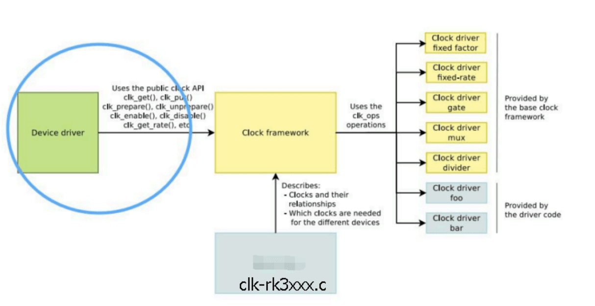
Main contents include (not all CLOCKs need to support):
- Enable/Disable CLOCK.
- Set the frequency of CLOCK.
- Select the Parent of CLOCK.
1.5 Code Structure
Table 1‑3 CLOCK Code Composition
| Item | Function | Path |
|---|---|---|
| clk-rk3xxx.c | .c mainly describes CLOCK registers, tree relationship between CLOCKs, etc. | drivers/clk/rockchip/clk-rk3xxx.c |
| rk3xxx-cru.h | .h defines CLOCK IDs, matches CLOCK Name by ID | include/dt-bindings/clock/rk3xxx-cru.h include/dt-bindings/clock/rockchip,rk3xxx-cru.h |
| RK special handling | Handles RK's PLL clocks, some special clocks such as LCDC, I2S, etc. | drivers/clk/rockchip/clk-xxx.c |
| CLK API | Provides interfaces for Driver calls in Linux environment | drivers/clk/clk-xxx.x |
The software framework of CLOCK consists of three parts: Device Tree of CLOCK (register description of CLOCK, tree relationship between CLOCKs, etc.), Device driver CLOCK configuration, and CLOCK API. The functions of these three parts and the code paths of CLOCK are shown in Table 1-1.
2. CLOCK Development Guide
2.1 Overview
This chapter describes how to modify clock configuration, use API interfaces, and debug CLOCK programs.
2.2 Clock Related Concepts
2.2.1 PLL
Phase Locked Loop, which is input by a 24M crystal oscillator, and then the internal PLL locks the corresponding frequency. This is the source of all CLOCKs in the SOC. All bus and device clocks of the SOC are divided down from the PLL. The main PLLs on the RK platform are:
Table 2‑1 PLL Description
| PLL | Sub-device | Purpose | Remarks |
|---|---|---|---|
| APLL | CLOCK_CORE | CPU clock | Generally only for CPU use, because CPU will change frequency, APLL will change according to CPU required frequency |
| DPLL | CLOCK_DDR | DDR clock | Generally only for DDR use, because DDR will change frequency, DPLL will change according to DDR requirements |
| GPLL | Provides backup for bus and peripheral clocks | Generally set at 594M or 1200M to ensure basic 100, 200, 300, 400M clocks are output | |
| CPLL | Backup for GMAC or other devices | Generally may be 400, 500, 800, 1000M. Or exclusively for Lcdc | |
| NPLL | Backup for other devices | Generally may be 1188M, or exclusively for Lcdc |
2.2.2 Bus
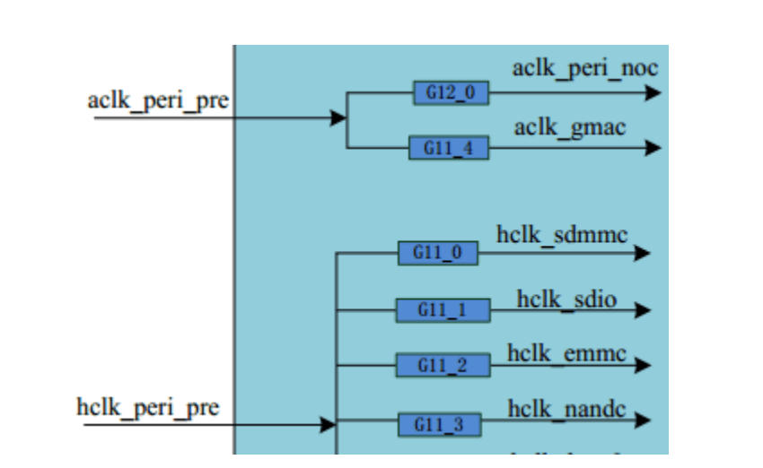
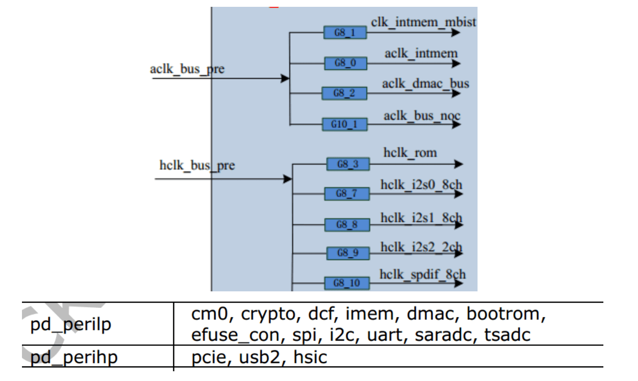
Our SOC buses include ACLK_PERI, HCLK_PERI, PCLK_PERI, ACLK_BUS, HCLK_BUS, PCLK_BUS. (ACLK is used for data transfer, PCLK and HCLK are generally used for register read/write)
The distinction between BUS and PERI is mainly to distinguish between high-speed and low-speed buses. ACLK range is 100-300M, PCLK range is 50M150M, HCLK range is 37M150M. Under BUS are mainly some low-speed devices, such as I2C, I2S, SPI, etc., while under PERI are generally EMMC, GMAC, USB, etc. Different chips may have some differences in design. For example: for some devices that require high bus speed, a separate ACLK may be designed for this device (such as ACLK_EMMC or ACLK_USB, etc.).
The bus clocks of each device will be attached to these clocks, as shown in the following structure:
Table 2‑2 Bus Clock Structure
Note:
On RK3399, high-speed and low-speed buses are completely separated, divided into high-speed: ACLK_PERIHP, HCLK_PERIHP, PCLK_PERIHP; low-speed: ACLK_PERILP0, HCLK_PERILP0, PCLK_PERILP0, HCLK_PERILP1, PCLK_PERILP1. This is for optimal power consumption, and different bus frequencies can be set according to different needs. (See the clock diagram for details of which device is under which bus)
You can refer to (EMMC, GMAC, USB, etc. have their own ACLK).
2.2.3 GATING
There are many GATINGs in the CLOCK framework, mainly used to reduce power consumption. When some devices are turned off and CLOCK is not needed, GATING can be turned off to save power.
The GATING of the RK CLOCK framework is structured as a tree with parent-child attributes. The GATING switch has a reference counting mechanism. When CLOCK is enabled, it will traverse and enable its parent CLOCK. When the child CLOCK is turned off, the parent CLOCK will traverse all child CLOCKs, and only when all children are turned off will the parent CLOCK be turned off.
(For example: When I2S2 is used, the three GATINGs in the figure (as shown in Figure 2-2) must be enabled, but in software, only the last level of GATING needs to be enabled, and the clock structure will automatically enable its parent GATING.)
Table 2‑3 GATING Example Diagram

2.3 Clock Configuration
2.3.1 Clock Initialization Configuration
Unlike LINUX3.10, after kernel 4.4, clock initialization uses "of_clk_set_defaults" and then parses "assigned clocks" to get the CLOCK ID, then gets the CLOCK Name, parses "assigned-clock-parents" to get the parent to be set, and parses "assigned-clock-rates" to get the frequency to be set.
- Frequency
Frequency set during CLOCK TREE initialization:
arch/arm64/dts/rockchip/rk33xx.dtsi
cru: clock-controller@ff760000 {
    compatible = "rockchip,rk3399-cru";
    reg = <0x0 0xff760000 0x0 0x1000>;
    #clock-cells = <1>;
    #reset-cells = <1>;
    assigned-clocks =
        <&cru ACLK_VOP0>, <&cru HCLK_VOP0>,
        <&cru ACLK_VOP1>, <&cru HCLK_VOP1>,
        <&cru ARMCLKL>, <&cru ARMCLKB>,
        <&cru PLL_GPLL>, <&cru PLL_CPLL>,
        <&cru PLL_NPLL>,
        <&cru ACLK_PERIHP>, <&cru HCLK_PERIHP>,
        <&cru PCLK_PERIHP>,
        <&cru ACLK_PERILP0>, <&cru HCLK_PERILP0>,
        <&cru PCLK_PERILP0>,
        <&cru HCLK_PERILP1>, <&cru PCLK_PERILP1>;
};
assigned-clock-rates =
    <400000000>, <200000000>,
    <400000000>, <200000000>,
    <816000000>, <816000000>,
    <594000000>, <800000000>,
    <1000000000>,
    <150000000>, <75000000>,
    <37500000>,
    <100000000>, <100000000>,
    <50000000>,
    <100000000>, <50000000>;
-
Parent
Parent set during CLOCK TREE initialization:
Note:
When configuring Parent and Rate for Assigned, they need to correspond one-to-one with Assigned-Clocks, because the setting is done by looking up and setting the CLK ID of Assigned Clocks. -
Gating
Whether CLOCK is enabled by default during CLOCK TREE initialization:
Note: For clocks that are not enabled by default and are not referenced by the device to enable, they will be turned off after CLOCK initialization is complete.
(1) Always-on CLOCK:
You need to add Critical configuration in clk-rk3xxx.c, mainly add the CLOCK Name that needs to be enabled by default in rk3399_cru_critical_clocks. Once added, the count of this CLOCK is increased by 1, and this CLOCK cannot be turned off later.
(2) When defining CLOCK, add the Flag attribute CLK_IGNORE_UNUSED. Even if this CLOCK is not used, it will not be turned off when unused CLOCKs are turned off at the end. However, the Enable Cnt seen in the CLOCK TREE is still 0, but the CLOCK is enabled.
(3) After kernel 6.1, always-on clk has changed, there are two ways
Enable all clk:
assigned-clock-parents =
    <&cru VPLL>, <&cru VPLL>,
    <&cru CPLL>, <&cru CPLL>,
    <&cru APLLL>, <&cru APLLB>,
    <&cru GPLL>, <&cru GPLL>,
    <&cru GPLL>,
    <&cru GPLL>, <&cru GPLL>;
static const char *const rk3399_cru_critical_clocks[] __initconst = {
    "aclk_usb3_noc",
    "aclk_gmac_noc",
    "pclk_gmac_noc",
    "pclk_center_main_noc",
    "aclk_cci_noc0",
    "aclk_cci_noc1",
    "clk_dbg_noc",
    "hclk_vcodec_noc",
    "aclk_vcodec_noc",
    "hclk_vdu_noc",
    "aclk_vdu_noc",
};
GATE(PCLK_PMUGRF_PMU, "pclk_pmugrf_pmu", "pclk_pmu_src", CLK_IGNORE_UNUSED,
RK3399_PMU_CLKGATE_CON(1), 1, GFLAGS),
Specify a particular clock to be always-on, add the Flag attribute CLK_IS_CRITICAL when defining CLOCK:
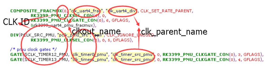
2.3.2 Clock ID
In LINUX4.4 and above, all CLOCK operations refer to CLOCK ID. How to get the ID?
Find the CLOCK you need to control in clk-rk3xxx.c (you can search by Name):
Table 2‑4 CLOCKID Example Diagram
2.3.3 Main CLOCK Registration Type Functions
Common types include:
- GATE: Describes GATING, mainly including CLOCK ID, type, GATING register offset address, BIT position, etc.
- MUX: Describes SELECT, mainly including CLOCK ID, type, MUX register offset address, BIT position, etc.
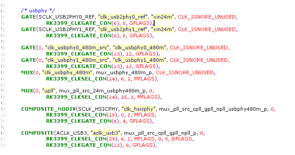
- COMPOSITE: Describes CLK with MUX, DIV, GATING, mainly including CLOCK ID, type, MUX, DIV, GATING register offset address, BIT position, etc.
Table 2‑5 CLOCKTYPE Example Diagram
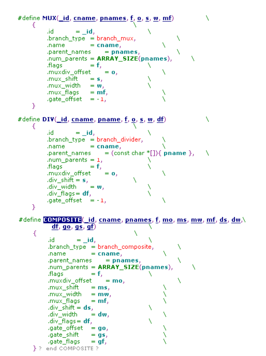
Table 2‑6 CLOCKPARENT Example Diagram
2.3.4 Driver Clock Configuration
- Get CLOCK pointer
- Add CLOCK reference information in DTS device node (recommended)
- DTS device node does not add CLOCK reference information
2.4 CLOCK API Interface
2.4.1 Main CLOCK API
- Header file
- Get CLOCK pointer
clocks = <&cru SCLK_TSADC>, <&cru PCLK_TSADC>;
clock-names = "tsadc", "apb_pclk";
dev->pclk = devm_clk_get(&pdev->dev, "tsadc");
dev->clk = devm_clk_get(&pdev->dev, "apb_pclk");
Driver code:
dev->pclk = devm_clk_get(NULL, "g_p_saradc");
dev->clk = devm_clk_get(NULL, "clk_saradc");
#include <linux/clk.h>
clk_prepare/clk_unprepare
clk_enable/clk_disable
clk_prepare_enable/clk_disable_unprepare
clk_get/clk_put
devm_clk_get/devm_clk_put
clk_get_rate/clk_set_rate
clk_round_rate
struct clk *devm_clk_get(struct device *dev, const char *id) (recommended, can be automatically released)
struct clk *clk_get(struct device *dev, const char *id)
static inline struct clk *devm_clk_get_optional(struct device *dev, const char *id)
static inline int __must_check devm_clk_bulk_get(struct device *dev, int num_clks, struct clk_bulk_data *clks) (recommended, get/set in bulk)
static inline int __must_check devm_clk_bulk_get_optional(struct device *dev, int num_clks, struct clk_bulk_data *clks)
static inline int __must_check devm_clk_bulk_get_all(struct device *dev, struct clk_bulk_data **clks)
-
Prepare/Enable CLOCK
You can use clk_prepare_enable/clk_disable_unprepare, clk_prepare_enable/clk_disable_unprepare (or clk_enable/clk_disable) must be used in pairs to ensure correct reference counting.
Note:
Explanation of prepare/unprepare, enable/disable:
The essence of these two sets of APIs is to divide the startup/stop of CLOCK into Atomic and Non-atomic stages for implementation and invocation. Therefore, the "will not sleep/may sleep" mentioned above has two meanings: one is to tell the underlying CLOCK Driver to put operations that may cause sleep into Prepare/Unprepare, and must not put them into Enable/Disable; the other is to remind the upper-layer Driver using CLOCK that calling Prepare/Unprepare may sleep, so do not call it in Atomic context (such as areas protected by Mutex lock, interrupt off, Spinlock, etc.), while calling Enable/Disable is safe.
Also, why does Enable/Disable of CLOCK need to sleep? For example, enabling PLL CLOCK, after starting PLL, you need to wait for it to stabilize. The PLL stabilization time is long, and during this time the CPU should be yielded (process sleeps), otherwise CPU will be wasted.
Finally, why are there combined clk_prepare_enable/clk_disable_unprepare interfaces? If the caller can ensure that it is called in Non-atomic context, prepare/enable and disable/unprepared can be called in sequence. For simplicity, the Framework encapsulates these two interfaces. -
Set CLOCK frequency
(Return value less than 0 means setting CLOCK failed)
2.4.2 Example
DTS
int clk_prepare(struct clk *clk)
/*Call before enabling clock, may cause sleep, so put sleep part here, atomic operations in enable*/
void clk_unprepare(struct clk *clk)
/*Reverse operation of prepare*/
int clk_enable(struct clk *clk)
/*Atomic operation, enable clock, this function must return after generating an actually usable clock signal*/
void clk_disable(struct clk *clk)
/*Atomic operation, disable clock*/
clk_enable/clk_disable, start/stop clock. Will not sleep.
clk_prepare/clk_unprepare, preparation before starting clock/cleanup after stopping clock. May sleep.
int clk_set_rate(struct clk *clk, unsigned long rate) (unit Hz)
tsadc: tsadc@ff260000 {
    compatible = "rockchip,rk3399-tsadc";
    reg = <0x0 0xff260000 0x0 0x100>;
    interrupts = <GIC_SPI 97 IRQ_TYPE_LEVEL_HIGH>;
    rockchip,grf = <&grf>;
    clocks = <&cru SCLK_TSADC>, <&cru PCLK_TSADC>;
    clock-names = "tsadc", "apb_pclk";
    assigned-clocks = <&cru SCLK_TSADC>;
};
Driver code
static int rockchip_thermal_probe(struct platform_device *pdev)
{
    .....
    thermal->reset = devm_reset_control_array_get(&pdev->dev, false, false);
    if (IS_ERR(thermal->reset)) {
        if (PTR_ERR(thermal->reset) != -EPROBE_DEFER)
            dev_err(&pdev->dev, "failed to get tsadc reset lines\n");
        return PTR_ERR(thermal->reset);
    }
    thermal->num_clks = devm_clk_bulk_get_all(&pdev->dev, &thermal->clks);
    if (thermal->num_clks < 1)
        return -ENODEV;
    error = clk_bulk_prepare_enable(thermal->num_clks, thermal->clks);
    if (error) {
        dev_err(&pdev->dev, "failed to prepare enable tsadc bulk clks: %d\n",
        error);
        return error;
    }
    ......
}
static int rockchip_thermal_remove(struct platform_device *pdev)
{
    .......
    clk_bulk_disable_unprepare(thermal->num_clks, thermal->clks);
    .......
}
2.5 CLOCK Debugging
- CLOCK DEBUGS:
Print the current clock tree structure:
cat /sys/kernel/debug/clk/clk_summary
get rate:
cat /sys/kernel/debug/clk_saradc/clk_rate
set rate:
echo 24000000 > /sys/kernel/debug/clk_saradc/clk_rate
Enable clk:
echo 1 > /sys/kernel/debug/clk_saradc/clk_enable_count
Disable clk:
echo 0 > /sys/kernel/debug/clk_saradc/clk_enable_count
Enable clk (kernel 6.1):
echo 1 > /sys/kernel/debug/clk_saradc/clk_prepare_enable
Disable clk (kernel 6.1):
echo 0 > /sys/kernel/debug/clk_saradc/clk_prepare_enable
-
CLOCK setting node:
Node command: -
TEST_CLK_OUT test:
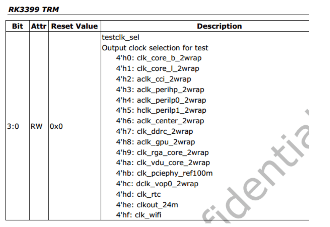
Some clocks can be output to test_clk_out to directly test the CLOCK output frequency, used to confirm whether certain clock waveforms are normal. Configuration method (take RK3399 as an example):
Table 2‑7 TESTCLK Example Diagram
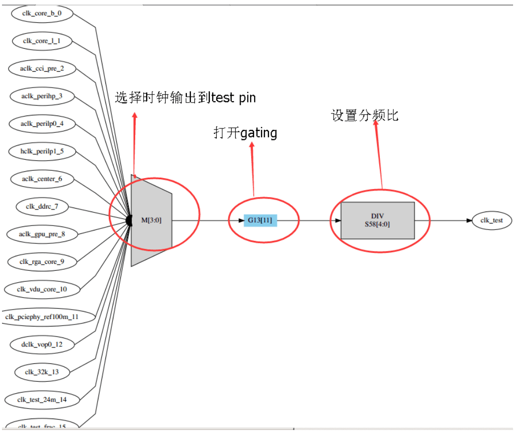
Set the MUX of CLOCK
CRU_MISC_CON
Address: Operational Base + offset (0x050c)
Table 2‑8 TESTCLOCK_MUX
Set the DIV of CLOCK
CRU_CLKSEL58_CON
Address: Operational Base + offset (0x01e8)
Table 2‑9 TESTCLOCK_DIV

Set the GATING of CLOCK
CRU_CLKGATE13_CON
Address: Operational Base + offset (0x0334)
Table 2‑10 TESTCLOCK_GATE

3. Common Problem Analysis
3.1 PLL Settings
3.1.1 PLL Frequency Table Definition
static struct rockchip_pll_rate_table rk3399_pll_rates[] = {
    /* _mhz, _refdiv, _fbdiv, _postdiv1, _postdiv2, _dsmpd, _frac */
    RK3036_PLL_RATE(2208000000, 1, 92, 1, 1, 1, 0),
    RK3036_PLL_RATE(2184000000, 1, 91, 1, 1, 1, 0),
    RK3036_PLL_RATE(2160000000, 1, 90, 1, 1, 1, 0),
    RK3036_PLL_RATE(2136000000, 1, 89, 1, 1, 1, 0),
    RK3036_PLL_RATE(2112000000, 1, 88, 1, 1, 1, 0),
    RK3036_PLL_RATE(2088000000, 1, 87, 1, 1, 1, 0),
    RK3036_PLL_RATE(2064000000, 1, 86, 1, 1, 1, 0),
    RK3036_PLL_RATE(2040000000, 1, 85, 1, 1, 1, 0),
    RK3036_PLL_RATE(2016000000, 1, 84, 1, 1, 1, 0),
    RK3036_PLL_RATE(1992000000, 1, 83, 1, 1, 1, 0),
    RK3036_PLL_RATE(1968000000, 1, 82, 1, 1, 1, 0),
    RK3036_PLL_RATE(1944000000, 1, 81, 1, 1, 1, 0),
    RK3036_PLL_RATE(1920000000, 1, 80, 1, 1, 1, 0),
    RK3036_PLL_RATE(1896000000, 1, 79, 1, 1, 1, 0),
    RK3036_PLL_RATE(1872000000, 1, 78, 1, 1, 1, 0),
    RK3036_PLL_RATE(1848000000, 1, 77, 1, 1, 1, 0),
    RK3036_PLL_RATE(1824000000, 1, 76, 1, 1, 1, 0),
    RK3036_PLL_RATE(1800000000, 1, 75, 1, 1, 1, 0),
    RK3036_PLL_RATE(1776000000, 1, 74, 1, 1, 1, 0),
    RK3036_PLL_RATE(1752000000, 1, 73, 1, 1, 1, 0),
    RK3036_PLL_RATE(1728000000, 1, 72, 1, 1, 1, 0),
    RK3036_PLL_RATE(1704000000, 1, 71, 1, 1, 1, 0),
    RK3036_PLL_RATE(1680000000, 1, 70, 1, 1, 1, 0),
    RK3036_PLL_RATE(1656000000, 1, 69, 1, 1, 1, 0),
    RK3036_PLL_RATE(1632000000, 1, 68, 1, 1, 1, 0),
    RK3036_PLL_RATE(1608000000, 1, 67, 1, 1, 1, 0),
    RK3036_PLL_RATE(1600000000, 3, 200, 1, 1, 1, 0),
    RK3036_PLL_RATE(1584000000, 1, 66, 1, 1, 1, 0),
    RK3036_PLL_RATE(1560000000, 1, 65, 1, 1, 1, 0),
    RK3036_PLL_RATE(1536000000, 1, 64, 1, 1, 1, 0),
    RK3036_PLL_RATE(1512000000, 1, 63, 1, 1, 1, 0),
    RK3036_PLL_RATE(1488000000, 1, 62, 1, 1, 1, 0),
    RK3036_PLL_RATE(1464000000, 1, 61, 1, 1, 1, 0),
    RK3036_PLL_RATE(1440000000, 1, 60, 1, 1, 1, 0),
    RK3036_PLL_RATE(1416000000, 1, 59, 1, 1, 1, 0),
    RK3036_PLL_RATE(1392000000, 1, 58, 1, 1, 1, 0),
    RK3036_PLL_RATE(1368000000, 1, 57, 1, 1, 1, 0),
    RK3036_PLL_RATE(1344000000, 1, 56, 1, 1, 1, 0),
    RK3036_PLL_RATE(1320000000, 1, 55, 1, 1, 1, 0),
    RK3036_PLL_RATE(1296000000, 1, 54, 1, 1, 1, 0),
    RK3036_PLL_RATE(1272000000, 1, 53, 1, 1, 1, 0),
    RK3036_PLL_RATE(1248000000, 1, 52, 1, 1, 1, 0),
    RK3036_PLL_RATE(1200000000, 1, 50, 1, 1, 1, 0),
    RK3036_PLL_RATE(1188000000, 2, 99, 1, 1, 1, 0),
};
3.1.2 PLL Calculation Formula
For example: VCO = 24M * 99 / 2 = 1188M
FOUT = 1188 / 2/ 1 = 594M
If you need to add other PLL frequencies, just complete the table according to the above formula.
There is a special type of PLL. If it cannot be found in the table, it will automatically calculate the PLL parameters. For example:
(Note: When using automatic calculation, VCO cannot be guaranteed to be as large as possible. If you have requirements for PLL jitter, it is not recommended to use.)
RK3036_PLL_RATE(1104000000, 1, 46, 1, 1, 1, 0),
RK3036_PLL_RATE(1100000000, 12, 550, 1, 1, 1, 0),
RK3036_PLL_RATE(1008000000, 1, 84, 2, 1, 1, 0),
RK3036_PLL_RATE(1000000000, 1, 125, 3, 1, 1, 0),
RK3036_PLL_RATE( 984000000, 1, 82, 2, 1, 1, 0),
RK3036_PLL_RATE( 960000000, 1, 80, 2, 1, 1, 0),
RK3036_PLL_RATE( 936000000, 1, 78, 2, 1, 1, 0),
RK3036_PLL_RATE( 912000000, 1, 76, 2, 1, 1, 0),
RK3036_PLL_RATE( 900000000, 4, 300, 2, 1, 1, 0),
RK3036_PLL_RATE( 888000000, 1, 74, 2, 1, 1, 0),
RK3036_PLL_RATE( 864000000, 1, 72, 2, 1, 1, 0),
RK3036_PLL_RATE( 840000000, 1, 70, 2, 1, 1, 0),
RK3036_PLL_RATE( 816000000, 1, 68, 2, 1, 1, 0),
RK3036_PLL_RATE( 800000000, 1, 100, 3, 1, 1, 0),
RK3036_PLL_RATE( 700000000, 6, 350, 2, 1, 1, 0),
RK3036_PLL_RATE( 696000000, 1, 58, 2, 1, 1, 0),
RK3036_PLL_RATE( 676000000, 3, 169, 2, 1, 1, 0),
RK3036_PLL_RATE( 600000000, 1, 75, 3, 1, 1, 0),
RK3036_PLL_RATE( 594000000, 1, 99, 4, 1, 1, 0),
RK3036_PLL_RATE( 533250000, 8, 711, 4, 1, 1, 0),
RK3036_PLL_RATE( 504000000, 1, 63, 3, 1, 1, 0),
RK3036_PLL_RATE( 500000000, 6, 250, 2, 1, 1, 0),
RK3036_PLL_RATE( 408000000, 1, 68, 2, 2, 1, 0),
RK3036_PLL_RATE( 312000000, 1, 52, 2, 2, 1, 0),
RK3036_PLL_RATE( 297000000, 1, 99, 4, 2, 1, 0),
RK3036_PLL_RATE( 216000000, 1, 72, 4, 2, 1, 0),
RK3036_PLL_RATE( 148500000, 1, 99, 4, 4, 1, 0),
RK3036_PLL_RATE( 106500000, 1, 71, 4, 4, 1, 0),
RK3036_PLL_RATE(  96000000, 1, 64, 4, 4, 1, 0),
RK3036_PLL_RATE(  74250000, 2, 99, 4, 4, 1, 0),
RK3036_PLL_RATE(  65000000, 1, 65, 6, 4, 1, 0),
RK3036_PLL_RATE(  54000000, 1, 54, 6, 4, 1, 0),
RK3036_PLL_RATE(  27000000, 1, 27, 6, 4, 1, 0),
{ /* sentinel */ },
};
VCO = 24M * FBDIV / REFDIV (450M ~ 2200M)
/* The larger the VCO, the smaller the jitter, the greater the power consumption; the smaller the REFDIV, the shorter the PLL LOCK time /
FOUT = VCO / POSTDIV1/ POSTDIV2 /
/ POSTDIV1 >= POSTDIV2*/
3.2 Settings for Some Special Clocks
3.2.1 LCDC Display Related Clocks
The DCLK of LCDC is determined by the current screen resolution, so there will be great differences between different products. Therefore, the DCLK of LCDC on the RK platform generally exclusively occupies a PLL. Since a PLL needs to be exclusively used, the frequency of this PLL will change according to the requirements of the screen. Therefore, this PLL generally requires automatic calculation of PLL parameters. Also, other clocks with clock requirements should not be attached under this PLL as much as possible. As shown in the table below:
Table 3‑1 DCLK Allocation Table
| Product Name | PLL |
|---|---|
| RK303X | Exclusive CPLL |
| RK312X | Exclusive CPLL |
| RK322X | Exclusive HDMIPHY PLL |
| RK3288X | Exclusive CPLL |
| RK3368 | Exclusive NPLL |
| RK3399 | Supports dual display, exclusive CPLL and VPLL |
| RK3568 | Supports 3 ports, exclusive HPLL and VPLL |
| RK3588 | Supports 4 ports, exclusive V0PLL, and 2 HDMIPHYPLL |
| RK3576 | Supports 3 ports, exclusive VPLL, and 1 HDMIPHYPLL |
| RK3506 | Supports 1 port, nearby frequency division |
For display CLOCK settings, there are great differences between platforms. Here, RK322X and RK3288 are taken as examples.
RK322X:
Use HDMIPHY PLL for DCLK LCDC, so it is relatively simple. Whatever DCLK LCDC needs, HDMIPHY outputs that clock, which is the PLL lock output implemented inside HDMIPHY.
RK3288:
RK3288 is more complicated. Although it also exclusively uses CPLL, there are other clocks under CPLL, and 3288 supports dual display, that is, there are DCLK_LCDC0 and DCLK_LCDC1, one for main display and one for HDMI display. Both main display and HDMI display are related to the actual screen resolution, so theoretically two independent PLLs are required, but 3288 is designed with only one PLL for display, so we can only require the main display to be able to modify the frequency of CPLL to meet the screen of any resolution, while the other lcdc can only divide the nearest frequency under the current GPLL and CPLL frequencies.
RK3399:
VPLL is used for HDMI, that is, the DCLK of the VOP for HDMI display needs to be bound to VPLL, and the DCLK and VPLL frequencies are 1:1. The other VOP is bound to CPLL. Dts can be configured as follows:
&vopb_rk_fb {
    assigned-clocks = <&cru DCLK_VOP0_DIV>;
    assigned-clock-parents = <&cru PLL_VPLL>;
};
&vopl_rk_fb {
    assigned-clocks = <&cru DCLK_VOP1_DIV>;
    assigned-clock-parents = <&cru PLL_CPLL>;
};
VOP0 for HDMI
&vopb_rk_fb {
    assigned-clocks = <&cru DCLK_VOP0_DIV>;
    assigned-clock-parents = <&cru PLL_CPLL>;
};
&vopl_rk_fb {
    assigned-clocks = <&cru DCLK_VOP1_DIV>;
    assigned-clock-parents = <&cru PLL_VPLL>;
};
3.2.2 Fractional Division
I2S, UART, etc. have fractional division. There is a requirement for fractional division settings: the frequency of fractional division and the parent of fractional division must have a 20 times relationship. If the 20 times relationship is not met, the output CLOCK will have large jitter and frequency offset.
Table 3‑2 Fractional Division Clock Diagram

3.2.3 Ethernet Clock
For Ethernet clocks, precision is generally required. 100M Ethernet requires a precise 50M frequency, and Gigabit Ethernet requires a precise 125M frequency. Generally, if Ethernet is required, the PLL must also output a precise clock. If the current clock scheme cannot output a precise clock for other reasons, Ethernet must use an external clock crystal oscillator. This is determined according to project requirements and actual product solutions.
3.2.4 PLL Parameter Clock Multi-path Input
The reference clock of RK3576 and RK3506 PLL supports both the original crystal oscillator input and the new IO input. It is mainly used with audio functions for synchronization. For detailed usage, please contact our support.