
USB
Overview
This document provides the development guide for the RK3588 USB module, aiming to help developers understand the hardware circuit design and software DTS configuration of the RK3588 USB controller and PHY, so that developers can flexibly design and quickly develop according to the USB application requirements of their products.
Chip Name | Kernel Version: RK3588, RK3588S | Linux-5.10 and above
Target Audience
This document (guide) is mainly intended for the following engineers:
- Technical Support Engineers
- Software Development Engineers
- Hardware Development Engineers
1. Introduction to RK3588 USB Controller and PHY
RK3588 supports 5 independent USB controllers, including: 2 USB 2.0 HOST controllers, 2 USB 3.1 OTG controllers, and 1 USB 3.1 HOST controller. Compared with RK3588, RK3588S has one less USB 3.1 OTG controller. The specific types of USB controllers are shown in Table 1 below. For more detailed USB controller features, please refer to the RK3588 datasheet.
Table 1 RK3588 USB Controller List
| Chip / USB Controller | 2.0 HOST (EHCI&OHCI) | USB 3.1 OTG (DWC3&xHCI) | USB 3.1 Host (xHCI) |
|---|---|---|---|
| RK3588 | 2 | 2 | 1 |
| RK3588S | 2 | 1 | 1 |
RK3588 supports 7 independent USB PHYs, including: 4 USB 2.0 PHYs, 2 USB 3.1/DP Combo PHYs, and 1 USB 3.1/SATA/PCIe Combo PHY. Compared with RK3588, RK3588S has one less USB 2.0 PHY and one less USB 3.1/DP Combo PHY.
Table 2 RK3588 USB PHY Support List
| Chip / PHY | USB 2.0 PHY | USB3.1/DP ComboPHY | USB 3.1/SATA/PCIe ComboPHY |
|---|---|---|---|
| RK3588 | 4 [1 × port] | 2 | 1 |
| RK3588S | 3 [1 × port] | 1 | 1 |
Note:
- In the table, the number N indicates support for N independent USB controllers and USB PHYs;
- In the table, [1 × ports] means one PHY supports only 1 USB port;
- In the table, "EHCI&OHCI" means the USB controller integrates both EHCI and OHCI controllers. "DWC3&xHCI" means the USB controller integrates both DWC3 and xHCI controllers;
- USB 3.1 Gen1 physical layer transmission rate is 5Gbps, USB 2.0 physical layer transmission rate is 480Mbps;
- USB 3.1/DP Combo PHY supports 4 x lanes and can simultaneously support USB 3.1 + DP 2 x lanes;
- USB 3.1/SATA/PCIe Combo PHY can only support one working mode at a time, i.e., USB3.1 and SATA/PCIe interfaces are mutually exclusive;
Table 3 RK3588 USB Controller and PHY Connection Relationship
| USB Interface Name (Schematic) | USB Controller | USB PHY |
|---|---|---|
| TYPEC0 | OTG0 (DWC3&xHCI) | USB3.1/DP Combo PHY0 + USB2.0 PHY0 |
| TYPEC1 | OTG1 (DWC3&xHCI) | USB3.1/DP Combo PHY1 + USB2.0 PHY1 |
| USB20_HOST0 | USB2.0 HOST0 (EHCI&OHCI) | USB2.0 PHY2 |
| USB20_HOST1 | USB2.0 HOST1 (EHCI&OHCI) | USB2.0 PHY3 |
| USB30_2 | USB3.1 HOST2 (xHCI) | USB3.1/SATA/PCIe ComboPHY2 |
The correspondence between RK3588 USB controllers and chip-side USB data pins is shown in Table 4 below.
Table 4 RK3588 USB Controller and USB Pin Correspondence
| USB Controller / Pin | RK3588 USB data pin |
|---|---|
| USB 2.0 HOST0 | USB20_HOST0_DP/USB20_HOST0_DM |
| USB 2.0 HOST1 | USB20_HOST1_DP/USB20_HOST1_DM |
| USB 3.1 OTG0 | TYPEC0_USB20_OTG_DP/TYPEC0_USB20_OTG_DM, TYPEC0_SSRX1P/TYPEC0_SSRX1N, TYPEC0_SSTX1P/TYPEC0_SSTX1N, TYPEC0_SSRX2P/TYPEC0_SSRX2N, TYPEC0_SSTX2P/TYPEC0_SSTX2N |
| USB 3.1 OTG1 | TYPEC1_USB20_OTG_DP/TYPEC1_USB20_OTG_DM, TYPEC1_SSRX1P/TYPEC1_SSRX1N, TYPEC1_SSTX1P/TYPEC1_SSTX1N, TYPEC1_SSRX2P/TYPEC1_SSRX2N, TYPEC1_SSTX2P/TYPEC1_SSTX2N |
| USB 3.1 HOST2 | USB30_2_SSTXP/USB30_2_SSTXN, USB30_2_SSRXP/USB30_2_SSRXN |
The internal connection relationship between RK3588 USB controllers and PHYs, as well as the corresponding common USB physical interfaces, is shown in Figure 1 below.
Figure 1 RK3588 USB Controller and PHY Connection Diagram
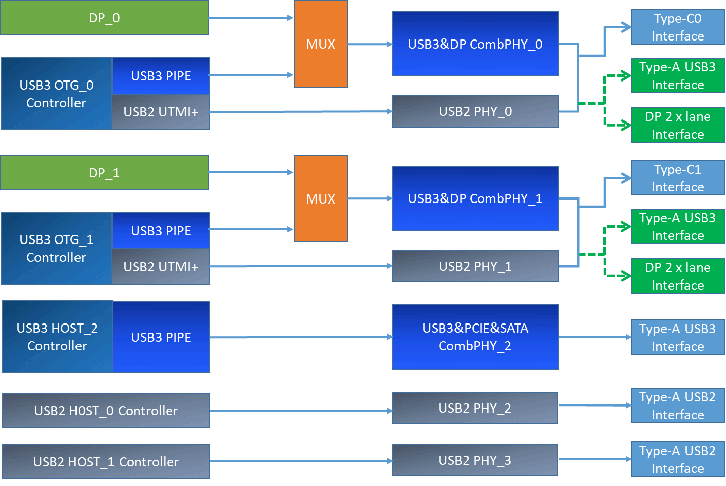
From Figure 1, it can be seen that:
- RK3588 can support up to 2 full-featured Type-C interfaces, 2 Type-A USB 2.0 interfaces, and 1 Type-A USB 3.1 only interface (not backward compatible with USB 2.0);
- The USB 3.1 OTG controller shares the USB3.1/DP Combo PHY with the DP controller, which can form a full-featured Type-C interface, or can be split for independent use (e.g., common Type-A USB 3.1 interface + DP interface [2 x lanes]);
- The USB 3.1 HOST_2 controller only supports USB 3.1 function and cannot support USB 2.0 (because it does not have a USB 2.0 PHY). USB 3.1 HOST2 can be combined with USB 2.0 HOST_0 or USB 2.0 HOST_1 as a complete Type-A USB 3.1 interface;
- USB 3.1/DP Combo PHY can only support USB 3.1 Gen1 and is not backward compatible with USB 2.0. Therefore, in the chip's internal design, it is actually combined with a USB 2.0 PHY to support the complete USB 3.1 protocol function. Among them, USB 3.1/DP Combo PHY0 is fixedly combined with USB2 PHY0, and USB 3.1/DP Combo PHY1 is fixedly combined with USB2 PHY1;
- USB 3.1/SATA/PCIe Combo PHY can only support USB 3.1 Gen1 and is not backward compatible with USB 2.0. Also, in the chip's internal design, it is not combined with a USB2 PHY. Therefore, USB3 HOST_2 needs to be combined with USB2 HOST_0/1 interface (choose one) to support the complete USB 3.1 protocol function;
- The difference between the USB modules of RK3588 and RK3588S is: compared with RK3588, RK3588S has one less set of Type-C1 (i.e., 1 USB 3.1 OTG controller + 1 DP controller + 1 USB3.1/DP Combo PHY + 1 USB 2.0 PHY);
It should be noted that the interface types supported by RK3588 USB are not limited to the Type-C/A USB interface types described in Figure 1, but can support all common USB interfaces, including Type-C USB 2.0/3.1, Type-A USB 2.0/3.1, Micro USB 2.0/3.1, etc. For specific information, please refer to the RK3588 USB supported interface types. In order to adapt to different USB circuit designs and interface types, the Linux - 5.10 kernel USB driver has already made software compatibility. Developers only need to correctly configure the Linux USB DTS according to the USB hardware circuit of the product to enable the corresponding USB interface function. For detailed USB DTS configuration methods, please refer to RK3588USB DTS configuration.
2. RK3588 Supported USB Interface Types
RK3588 USB can support the common USB interface types shown in Figure 2 below. During product design, you can flexibly design the USB hardware circuit according to the actual application scenario requirements, and only need to adapt the Linux USB DTS.
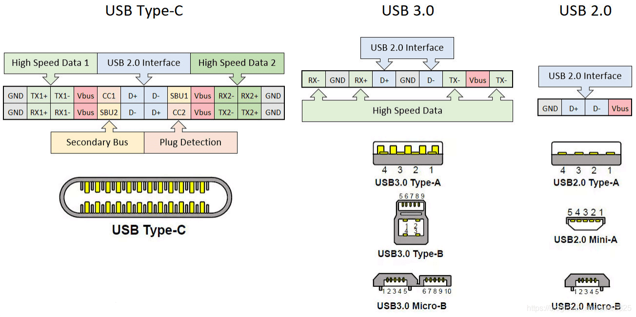
Figure 2 USB Interface Types
2.1 Type-C Interface Types
2.1.1 Type-C USB 3.1/DP Full-Function Interface
RK3588 Type-C0/1 can support full-function Type-C interface features [1], as shown in Figure 3 below. For specific hardware circuit design, please refer to the Type-C USB 3.1/DP full-function hardware circuit. The main supported features are as follows:
- Supports Type-C PD (requires external Type-C controller chip)
- Supports USB 3.1 Gen1 5Gbps data transmission
- Supports DP Alternate Mode
Figure 3 Type-C USB 3.1/DP Interface
Figure 4 Type-C Interface Pin Definition
Table 5 Type-C Interface Description
| Pin | Name | Description | Pin | Name | Description |
|---|---|---|---|---|---|
| A1 | GND | Ground | B12 | GND | Ground |
| A2 | SSTXp1 | SuperSpeed differential signal TX1+ | B11 | SSRXp1 | SuperSpeed differential signal RX1+ |
| A3 | SSTXn1 | SuperSpeed differential signal TX1- | B10 | SSRXn1 | SuperSpeed differential signal RX1- |
| A4 | VBUS | USB bus power | B9 | VBUS | USB bus power |
| A5 | CC1 | Configuration channel | B8 | SBU2 | Sideband use (SBU) |
| A6 | Dp1 | USB 2.0 differential signal D1+ | B7 | Dn2 | USB 2.0 differential signal D2- |
| A7 | Dn1 | USB 2.0 differential signal D1- | B6 | Dp2 | USB 2.0 differential signal D2+ |
| A8 | SBU1 | Sideband use (SBU) | B5 | CC2 | Configuration channel |
| A9 | VBUS | USB bus power | B4 | VBUS | USB bus power |
| A10 | SSRXn2 | SuperSpeed differential signal RX2- | B3 | SSTXn2 | SuperSpeed differential signal TX2- |
| A11 | SSRXp2 | SuperSpeed differential signal RX2+ | B2 | SSTXp2 | SuperSpeed differential signal TX2+ |
| A12 | GND | Ground | B1 | GND | Ground |
Table 6 RK3588 Type-C0 and Type-C Interface Connection Relationship
| RK3588 Type-C0 Pin | Type-C Interface Pin | Relationship Description |
|---|---|---|
| TYPEC0_SSRX1P/DP0_TX0P | B10/B11 | Connected to RK3588 USBDP PHY lane, can be used for USB 3.1 Rx or DP Tx |
| TYPEC0_SSRX1N/DP0_TX0N | ||
| TYPEC0_SSTX1P/DP0_TX1P | A2/A3 | Connected to RK3588 USBDP PHY lane, can be used for USB 3.1 Tx or DP Tx |
| TYPEC0_SSTX1N/DP0_TX1N | ||
| TYPEC0_SSRX2P/DP0_TX2P | A10/A11 | Connected to RK3588 USBDP PHY lane, can be used for USB 3.1 Rx or DP Tx |
| TYPEC0_SSRX2N/DP0_TX2N | ||
| TYPEC0_SSTX2P/DP0_TX3P | B2/B3 | Connected to RK3588 USBDP PHY lane, can be used for USB 3.1 Tx or DP Tx |
| TYPEC0_SSTX2N/DP0_TX3N | ||
| TYPEC0_OTG_DP/DM | A6/A7, B6/B7 | Connected to RK3588 TYPEC0_OTG_DP, where A6 and B6 are paralleled, A7 and B7 are paralleled |
| TYPEC0_SBU1/TYPEC0_SBU2 | A8/B8 | Connected to RK3588 GPIO, used for software DP AUX transmission pull-up. No requirement for GPIO pull-up/down |
| TYPEC0_CC1/TYPEC0_CC2 | A5/B5 | Connected to external Type-C controller chip (HUSB311/FUSB302), not connected to SoC |
2.1.2 Type-C to Type-A USB 3.1/DP Interface
RK3588 Type-C0/1 can be split into independent Type-A USB 3.1 interface and DP interface.
For specific hardware circuit design, please refer to the Type-C to Type-A USB 3.1/DP hardware circuit.
Taking the Type-C to Type-A USB 3.1/DP interface design of RK3588 EVB2 as an example:
- Type-C0: Type-A USB 3.1 (using USBDP PHY0 lane0/1) + DP 1.4 (using USBDP PHY0 lane2/3);
- Type-C1: Type-A USB 3.1 (using USBDP PHY1 lane0/1) + DP to VGA (using USBDP PHY1 lane2/3);
Note:
In theory, hardware can allocate Type-A USB 3.1 to use lane2/3 and DP to use lane0/1. At the same time, software only needs to modify the property rockchip,dp-lane-mux of the Linux usbdp_phy node for adaptation.
2.1.3 Type-C to Type-A USB 2.0/DP Interface
RK3588 Type-C0/1 can be split into independent Type-A USB 2.0 interface and DP (4 x Lane) interface. For specific hardware circuit design, please refer to the Type-C to Type-A USB 2.0/DP hardware circuit. Taking the Type-C1 to Type-A USB 2.0/DP interface design of RK3588 NVR DEMO board as an example: Type-C1: Type-A USB 2.0 (not using USBDP PHY) + DP 4 x lane to HDMI2.0 (using USBDP PHY1 lane0/1/2/3)
2.1.4 Type-C USB 2.0 only Interface
RK3588 Type-C0/1 can be simplified to a Type-C USB 2.0 only interface. As shown in Figure 5 below:
- Supports Type-C PD (requires external Type-C controller chip)
- Supports USB 2.0 480Mbps data transmission
- Does not support DP Alternate Mode
This design mainly aims to simplify the hardware circuit design, but will reduce the maximum USB transmission rate. At the same time, to adapt to this interface design, significant modifications to the Linux USB DTS are required. Please refer to the Type-C USB 2.0 only DTS configuration.
Figure 5 Type-C USB 2.0 only Interface
2.2 Type-A Interface Types
2.2.1 Type-A USB 3.1 Interface
RK3588 can support up to 3 Type-A USB 3.1 interfaces, including:
- Type-C0 to Type-A USB 3.1
- Type-C1 to Type-A USB 3.1
- USB3_HOST2 + USB 2.0 HOST0/1
For specific hardware circuit design, please refer to the Type-A USB 3.1 hardware circuit.
Figure 6 Type-A USB 3.1 Interface
2.2.2 Type-A USB 2.0 Interface
RK3588 can support up to 4 Type-A USB 2.0 interfaces, including:
- Type-C0 to Type-A USB 2.0
- Type-C1 to Type-A USB 2.0
- USB 2.0 HOST0
- USB 2.0 HOST1
For specific hardware circuit design, please refer to the Type-A USB 2.0 hardware circuit.
Figure 7 Type-A USB 2.0 Interface
2.3 Micro Interface Types
2.3.1 Micro USB 3.1 Interface
RK3588 Type-C0/1 can support Micro USB 3.1 interface design. However, considering that the PCB area occupied by the Micro USB 3.1 interface is relatively large, it is currently rarely used in products.
The difference between Micro USB 3.1 and Type-A USB 3.1 pins is mainly the addition of the OTG ID pin, which is used for hardware automatic detection of ID level and switching OTG Device/HOST mode. The OTG ID pin needs to be connected to the RK3588 USB20_OTG_ID pin. In the chip, the ID is already pulled up to a high level of 1.8V by default, and no external pull-up is required.
Figure 8 Micro USB 3.1 Interface
2.3.2 Micro USB 2.0 Interface
RK3588 Type-C0 can support Micro USB 2.0 interface design. This design mainly aims to simplify the hardware circuit design, but will reduce the maximum USB transmission rate.
The difference between Micro USB 2.0 and Type-A USB 2.0 pins is mainly the addition of the OTG ID pin, which is used for hardware automatic detection of ID level and switching OTG Device/HOST mode. The OTG ID pin needs to be connected to the RK3588 USB20_OTG_ID pin. In the chip, the ID is already pulled up to a high level of 1.8V by default, and no external pull-up is required.
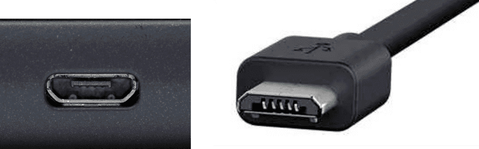
Figure 9 Micro USB 2.0 Interface
3. RK3588 USB Config Map
The 5 independent USB controllers and 7 independent USB PHYs of RK3588 can support the configuration methods listed in Figure 10 below.
Type-C0/1 can support 4 configurations:
- Config0: Type-C0 with DP function
- Config1: USB 2.0 OTG + DP 4 x Lane (Swap off)
- Config2: USB 2.0 OTG + DP 4 x Lane (Swap on)
- Config3: USB 3.1 OTG + DP 2 x Lane (Swap on)
- Config4: USB 3.1 OTG + DP 2 x Lane (Swap off)
USB 2.0 HOST0/1 and USB3_HOST2 supported configurations:
- Config0: USB 2.0 HOST0 + USB 2.0 HOST1 (USB3_HOST2 not used)
- Config2: USB 2.0 HOST0 Combo with USB3_HOST2 + USB 2.0 HOST1
- Config2: USB 2.0 HOST0 Combo with USB3_HOST2 + USB 2.0 HOST1
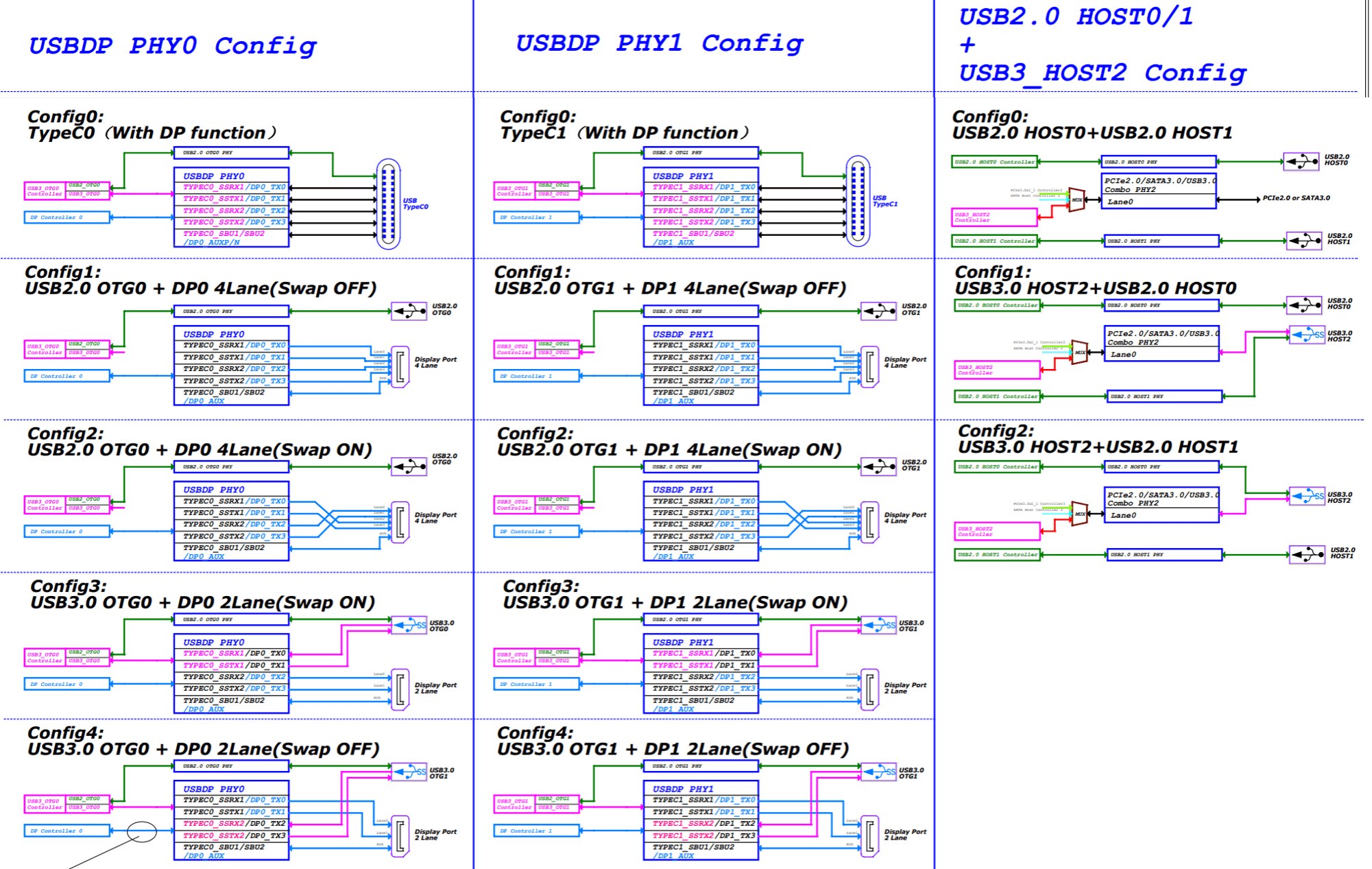
Figure 10 RK3588 USB Config Map
For more detailed USB configuration tables, please refer to the USB Controller Configure Table in the SDK EVB reference schematic.
It should be noted that the 4 lanes of the DP controller and USBDP PHY support arbitrary mapping, as shown in Figure 11 below. You only need to modify the DTS of the USBDP PHY for adaptation. If developers are not clear on how to adapt in software, it is recommended to refer to the conventional configurations listed in Figure 10 for hardware circuit design.
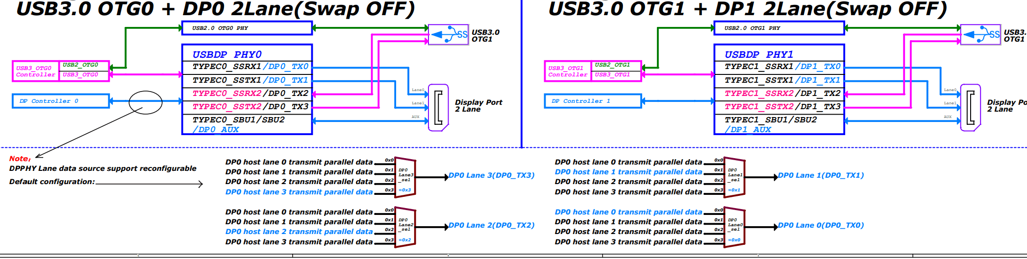
Figure 11 RK3588 DP Lane Map
4. RK3588 USB Hardware Circuit Design
This chapter mainly explains the various hardware circuit design schemes that RK3588 USB can support in practical applications. As shown in Figure 12 below, which is the RK3588 USB interface block diagram, it can be seen that RK3588 can support the following interfaces:
- USB20 HOST0
- USB20 HOST1
- USB30/DP1.4 MULTI0
- USB30/DP1.4 MULTI1
- USB30/PCIE2.0/SATA30 MULTI2
RK3588S has one less set of USB30/DP1.4 MULTI1 interfaces.
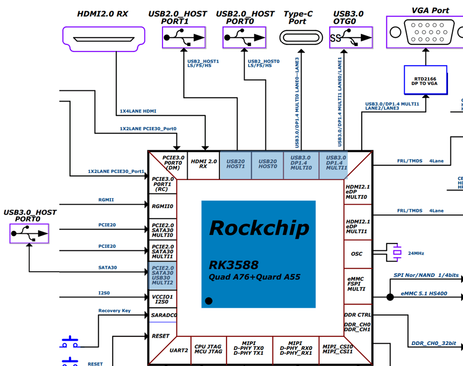
Figure 12 RK3588 USB Interface Block Diagram
4.1 USB Controller Power Supply and Power Management
The power supply for the RK3588 USB controller is VDD_LOGIC. At the same time, the chip internally designs a dedicated power domain for the USB controller. The corresponding Power Domain for each USB controller is shown in Table 7 below.
Table 7 USB Controller and PD Correspondence
| USB Controller | Power Domain |
|---|---|
| USB 2.0 HOST0/1 | PD_USB |
| USB 3.1 OTG0/1 | PD_USB |
| USB 3.1 HOST2 | PD_PHP |
In actual use scenarios, the Linux USB controller driver will dynamically switch the PD of the USB controller based on the working status of the USB interface, using the Linux PM Runtime mechanism to reduce the power consumption of the USB controller. When the system enters secondary standby, in order to achieve optimal power consumption, the software will forcibly turn off all PDs of the USB controller. Therefore, in actual product application scenarios, if you need to maintain the register working status of the USB controller during secondary standby, you need to call the function device_init_wakeup in the USB controller driver to avoid turning off the PD of the USB controller during secondary standby.
The power control strategy for the USB controller is as follows:
- For unused USB controllers, configure the corresponding controller DTS node as disabled.
- For USB controllers enabled in the kernel, the kernel USB driver already supports the USB controller Auto suspend function. When the USB HOST interface is not connected to any external device, the controller automatically enters suspend low-power state. Therefore, developers do not need to debug the dynamic power management of the USB controller.
The method to disable USB 2.0 HOST0/1 in the kernel is as follows:
# Disable USB 2.0 HOST0
&usb_host0_ehci { status = "disabled"; };
&usb_host0_ohci { status = "disabled"; };
# Disable USB 2.0 HOST1
&usb_host1_ehci { status = "disabled"; };
&usb_host1_ohci { status = "disabled"; };
4.2 USB PHY Power Supply and Power Management
4.2.1 USB 2.0 PHY Power Supply and Power Management
RK3588 supports 4 independent USB 2.0 PHYs. Compared with RK3588, RK3588S has one less USB 2.0 PHY1. Internally, all USB 2.0 PHYs belong to PD_BUS (Alive), and all USB 2.0 PHYs share the 3 power supply rails shown in Figure 13 below. Therefore, during system operation, it is not possible to reduce the power consumption of the USB 2.0 PHY by simply cutting off the power supply or turning off the PD.
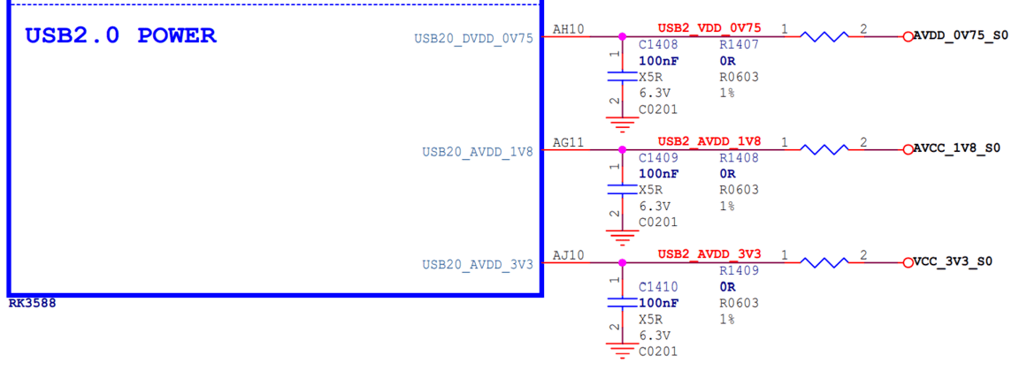
Figure 13 USB 2.0 PHY Power Supply
It should be noted that in actual circuits, if the supply voltage of the USB 2.0 PHY exceeds the specified maximum value or is lower than the specified minimum value, it may cause abnormal USB connection.
Table 8 USB 2.0 PHY Power Supply Voltage Requirements
| Power Supply | Minimum | Normal | Maximum | Unit |
|---|---|---|---|---|
| USB20_DVDD_0V75 | 0.6975 | 0.75 | 0.825 | V |
| USB20_AVDD_1V8 | 1.674 | 1.8 | 1.98 | V |
| USB20_AVDD_3V3 | 3.069 | 3.3 | 3.63 | V |
USB 2.0 PHY Power Control Strategy:
- To support Maskrom USB firmware download function, the power supply of USB 2.0 PHY must be normal.
- After the system is powered on, all USB 2.0 PHYs are in Normal mode by default. In the U-Boot SPL stage, the software configures USB 2.0 PHY1/PHY2/PHY3 to the lowest power IDDQ mode (SDK already supports this). After entering the system, the kernel USB driver will set the corresponding USB 2.0 PHY to exit IDDQ mode according to application requirements.
- For unused USB 2.0 PHYs, configure the corresponding USB 2.0 PHY DTS node as disabled (refer to Table 9).
- For USB 2.0 PHYs enabled in the kernel, the kernel USB 2.0 PHY driver will automatically perform dynamic power control on the PHY. When a device is detected to be inserted, the USB 2.0 PHY is automatically set to Normal mode. When no device is detected, the USB 2.0 PHY is automatically set to Suspend mode.
Table 9 USB 2.0 PHY Power Consumption Data (statistics for a single USB 2.0 PHY)
| Power Supply | Data Transfer | Dynamic Suspend PHY | disabled | Secondary Standby | Unit |
|---|---|---|---|---|---|
| USB20_DVDD_0V75 | 7.1 | 2.6 | 0.05 | 0 | mA |
| USB20_AVDD_1V8 | 17.8 | 3.1 | 0.05 | 0 | mA |
| USB20_AVDD_3V3 | 3.3 | 0.05 | 0.05 | 0 | mA |
Note:
- Data transfer power consumption test scenario: copying data with U2 drive connected, PHY in Normal mode;
- Dynamic suspend power consumption test scenario: USB 2.0 PHY DTS enabled, but no USB device connected, PHY in Suspend mode;
- PHY disabled power consumption test scenario: USB 2.0 PHY DTS disabled, PHY in IDDQ mode;
- Secondary standby power consumption test scenario: all three power supplies of USB 2.0 PHY are turned off;
Table 10 USB 2.0 PHY and USB Controller Connection Relationship
| USB 2.0 PHY | USB Controller |
|---|---|
| USB 2.0 PHY0 | USB 3.1 OT |
| USB 2.0 PHY1 | USB 3.1 OT |
| USB 2.0 PHY2 | USB 2.0 HO |
| USB 2.0 PHY3 | USB 2.0 HO |
The method to disable USB 2.0 PHY2/3 in the kernel is as follows:
&u2phy2 { status = "disabled"; };
&u2phy3 { status = "disabled"; };
&u2phy2_host { status = "disabled"; };
&u2phy3_host { status = "disabled"; };
4.2.2 USB 3.1 PHY Power Supply and Power Management
RK3588 supports two types of USB 3.1 Combo PHY:
- USB 3.1/DP Combo PHY
- USB 3.1/SATA/PCIe Combo PHY
Table 11 USB 3.1 Combo PHY and USB Controller Connection Relationship
| USB 3.1 Combo PHY | USB Controller |
|---|---|
| USB 3.1/DP Combo PHY0 | USB 3.1 OTG0 |
| USB 3.1/DP Combo PHY1 | USB 3.1 OTG1 |
| USB 3.1/SATA/PCIe Combo PHY2 | USB 3.1 HOST2 |
These two types of USB 3.1 Combo PHY correspond to different power supplies and power control methods, which are explained separately below.
4.2.2.1 USB 3.1/DP Combo PHY
RK3588 supports two independent USB 3.1/DP Combo PHYs. Compared with RK3588, RK3588S has one less USB 3.1/DP Combo PHY1. Internally, both USB 3.1/DP Combo PHYs belong to PD_BUS (Alive). Externally, the two PHYs have independent power supply pins, as shown in Figure 14 below.
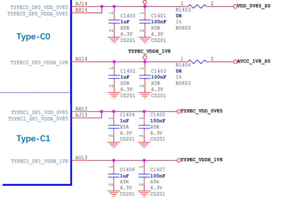
Figure 14 RK3588 USB 3.1/DP Combo PHY Power Supply
Table 12 USB 3.1/DP Combo PHY Power Supply Voltage Requirements
| Power Supply | Minimum | Normal | Maximum | Unit |
|---|---|---|---|---|
| VDD_0V85/VDDA_0V85 | 0.8075 | 0.85 | 0.8925 | V |
| VDDH_1V8 | 1.71 | 1.8 | 1.89 | V |
USB 3.1/DP Combo PHY Power Control Strategy:
- To support Maskrom USB firmware download function, the power supply of Type-C0 USBDP PHY0 must be normal.
- When the Type-C1 interface is not used, the corresponding Type-C1 USBDP PHY1 can be powered off.
- After the system is powered on, the USBDP PHY is in the lowest power state when uninitialized.
- For unused USBDP PHYs, configure the corresponding USBDP PHY DTS node as disabled, i.e., let the PHY be in the uninitialized state, which has the lowest power consumption.
- For USBDP PHYs enabled in the kernel, the kernel USBDP PHY driver will automatically perform dynamic power control on the PHY. When a device is detected to be inserted, the USBDP PHY is automatically set to P0 State. When no device is detected, the USBDP PHY is automatically set to P3 State (for Type-A interface) or reset state (for Type-C interface).
Table 13 USB 3.1/DP Combo PHY Power Consumption Data (statistics for a single USB 3.1/DP Combo PHY)
| Power Supply | Data Transfer | Dynamic Suspend [1] | Dynamic Suspend [2] | PHY disabled | Secondary Standby | Unit |
|---|---|---|---|---|---|---|
| VDD_0V85/VDDA_0V85 | 115.7 | 6.8 | 7.9 | 2 | 0 | mA |
| VDDH_1V8 | 29.4 | 0 | 2 | 0 | 0 | mA |
Note:
- Data transfer power consumption test scenario: copying data with U3 drive connected, PHY in P0 state;
- Dynamic suspend power consumption [1] test scenario: Type-C interface, no USB device connected, PHY in reset state;
- Dynamic suspend power consumption [2] test scenario: Type-A interface, no USB device connected, PHY in P3 state;
- PHY disabled power consumption test scenario: PHY DTS node configured as disabled, PHY in uninitialized state, lowest power consumption;
- Secondary standby power consumption test scenario: both power supplies of the PHY are turned off;
The method to disable USBDP PHY1 in the kernel is as follows:
&usbdp_phy1 { status = "disabled"; };
&usbdp_phy1_dp { status = "disabled"; };
&usbdp_phy1_u3 { status = "disabled"; };
4.2.2.2 USB 3.1/SATA/PCIe Combo PHY
RK3588 supports one USB3.1/SATA/PCIe Combo PHY. Internally, this PHY belongs to PD_BUS (Alive). Externally, the PHY has an independent power supply, as shown in Figure 15.
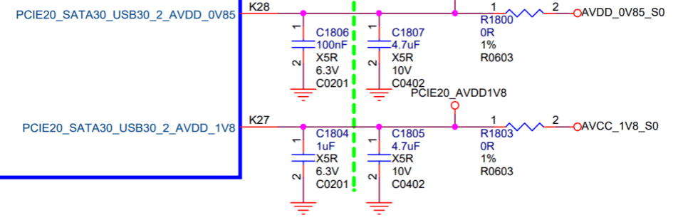
Figure 15 RK3588 USB 3.1/SATA/PCIe Combo PHY Power Supply
Table 14 USB 3.1/SATA/PCIe Combo PHY Power Supply Voltage Requirements
| Power Supply | Min | Typical | Max | Unit |
|---|---|---|---|---|
| AVDD_0V85 | 0.8 | 0.85 | 0.935 | V |
| AVDD_1V8 | 1.62 | 1.8 | 1.98 | V |
Power consumption control strategy for USB 3.1/SATA/PCIe Combo PHY:
- When the chip is powered on, the USB 3.1/SATA/PCIe Combo PHY is in working state by default. In the U-Boot SPL stage, software configures the PHY to reset state to keep it at the lowest power consumption. After entering the kernel, the USB controller driver releases the PHY reset by calling the rockchip_combphy_init() function.
- Dynamic power control of the PHY: When the Combo PHY works in USB mode, the PIPE state (P0/P1/P2/P3) is automatically controlled by the USB controller hardware, dynamically entering and exiting P0/P1/P2/P3 states according to different scenarios. For example, when no USB device is inserted, the PIPE is in P3 state; when a U3 disk is inserted, it switches to P0 state; when a U3 HUB is connected, as long as no other USB device is connected to the downstream port of the HUB, the PIPE state will automatically enter P3 low power state. When a USB device is inserted into the U3 HUB, the PIPE state automatically switches to P0. (Note: P0 is normal working state, P3 is the lowest power state)
- When the USB 3.1 HOST2 interface is clearly not used, the corresponding USB 3.1/SATA/PCIe Combo PHY can be powered off.
- If the PHY is powered, but not used, configure the corresponding PHY DTS node as disabled, i.e., keep the PHY in reset state for lowest power consumption.
Table 15 USB 3.1/SATA/PCIe Combo PHY Power Consumption Data
| Power Supply | Read/Write Data | Dynamic Sleep PHY disabled | Secondary Standby | Unit |
|---|---|---|---|---|
| AVDD_0V85 | 43.4 | 43.3 0.4 | 0 | mA |
| AVDD_1V8 | 4.3 | 4.1 0.2 | 0 | mA |
The method to disable USB 3.1/SATA/PCIe Combo PHY in the kernel is as follows:
&combphy2_psu {
    status = "disabled";
};
4.3 USB Hardware Circuit Design
4.3.1 TYPEC0_USB20_VBUSDET Circuit Design
TYPEC0_USB20_VBUSDET is used for USB Device scenarios to detect USB Device connection and disconnection. Design notes for TYPEC0_USB20_VBUSDET are as follows:
-
When Type-C0 is designed to support PD function with an external Type-C controller chip (e.g., FUSB302 or HUSB311), refer to the circuit design of RK3588 EVB1 Type-C0 (TYPEC0_USB20_VBUSDET is pulled up to VCC_3V3_S0). The software driver can detect USB Device connection and disconnection through the CC of the Type-C controller chip.
-
For other designs without an external Type-C controller chip (e.g., Type-C0 USB 2.0 only, Type-A USB 3.1, Micro USB 2.0/3.1), TYPEC0_USB20_VBUSDET should still use a traditional voltage divider circuit connected to the VBUS pin of the USB interface. VBUSDET should not be always powered (if USB HOST is needed, use a separate GPIO or PMIC VBUS control, not shared with other USB HOST interfaces).
-
The high-level range at the chip input end of TYPEC0_USB20_VBUSDET should be [0.9V ~ 3.3V].
4.3.2 Maskrom USB Circuit Design
RK3588 Maskrom uses Type-C0 USB 2.0 as the fixed firmware download function. The relevant circuit design is shown in Figure 16. To ensure the Maskrom USB download function works properly, the following requirements must be met:
- TYPEC0_USB20_VBUSDET must support external pull-up and cannot be left floating.
- The power supply for TypeC0 USBDP PHY (TYPEC0_DP0_VDD_0V85/TYPEC0_DP0_VDDA_0V85/TYPEC0_DP0_VDDH_1V8) and the external reference resistor (TYPEC0_DP0_REXT) must be properly connected. After entering the system, software will put the TypeC0 USBDP PHY into low power mode.
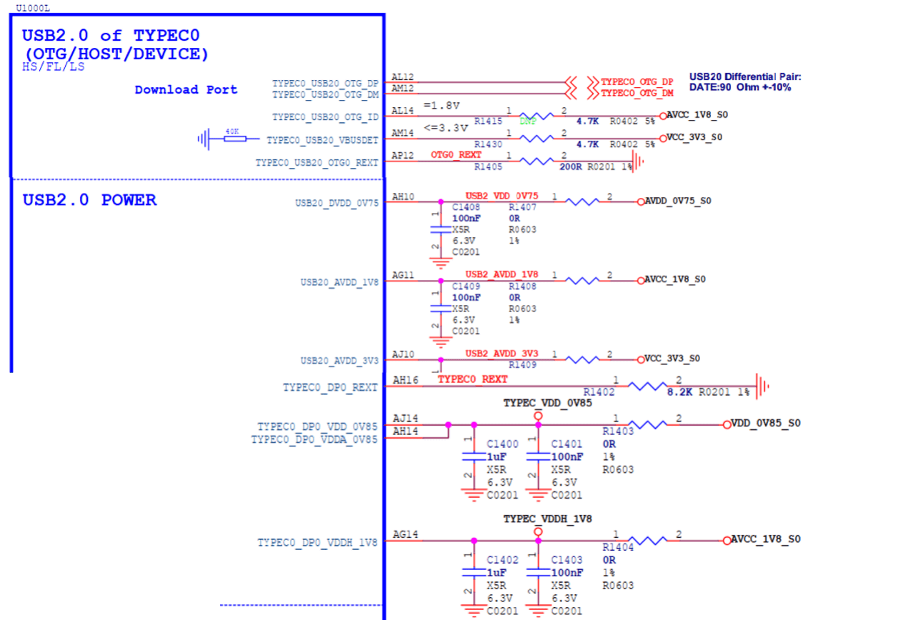
Figure 16 RK3588 Maskrom USB2 Firmware Download Port Circuit
4.3.3 Type-C USB 3.1/DP Full-Function Hardware Circuit
This solution applies to RK3588 Type-C0 and Type-C1.
Taking the RK3588 EVB1 Type-C0 hardware circuit design as an example:
- For the detailed connection between each pin of RK3588 Type-C0 and the Type-C interface, refer to Table 5 of the Type-C USB 3.1/DP full-function interface.
- The Type-C circuit needs to work with an external Type-C controller chip to achieve full Type-C functionality (including orientation detection, high-voltage/high-current PD protocol, etc.). RK3588 supports most common Type-C controller chips; see the Type-C controller chip support list for details.
- To support high-voltage charging and reduce hardware risks, TYPEC0_USB20_VBUSDET should not be connected to the VBUS of the Type-C interface, but should be pulled up to 3.3V (as shown in Figure 17, TYPEC0_USB20_VBUSDET is connected to VCC_3V3_S0), but must not be left floating.
- TYPEC0_USB20_OTG_ID is only used for OTG function of Micro interfaces and should be left floating for Type-C circuits.
- TYPEC0_SBU1/TYPEC0_SBU2 are only used for AUX communication in DP Alternate Mode. According to the AUX protocol, SBU1/SBU2 need to be pulled up according to the orientation of the Type-C insertion. Since RK3588 does not implement automatic pull-up for SBU1/SBU2 internally, the external hardware circuit must add two GPIO controls (corresponding to TYPEC0_SBU1_DC/TYPEC0_SBU2_DC in Figure 19). There is no requirement for the default pull-up/down of the GPIOs; any GPIO can be used. In software, modify the sbu1-dc-gpios and sbu2-dc-gpios properties of the usbdp_phy node for adaptation.
- For Type-C USB DTS software configuration, refer to the Type-C USB 3.1/DP full-function DTS configuration.
Figure 17 RK3588 Type-C0 Circuit
Figure 18 RK3588 Type-C0 PD Controller and VBUS Control Circuit
Figure 19 RK3588 Type-C0 Interface
4.3.4 Type-C to Type-A USB 3.1/DP Hardware Circuit
This solution applies to RK3588 Type-C0 and Type-C1, and can be split into independent Type-A USB 3.1 and DP (2 x Lane) interfaces.
Taking the RK3588 EVB2 Type-C0 to Type-A USB 3.1/DP hardware circuit design as an example:
- Type-A USB 3.1 uses TYPEC0_SSRX1P/N and TYPEC0_SSTX1P/N (corresponding to lane0/1 of the internal USBDP PHY), while DP uses DP0_TX2P/N and DP0_TX3P/N (corresponding to lane2/3 of the internal USBDP PHY).
- If USB OTG is used for Device/HOST scenarios, it is recommended that TYPEC0_OTG_VBUSDET be connected to the VBUS of the Type-A USB interface through a 30KΩ resistor.
- The power supply for Type-A VBUS (VCC5V0_USB30_HOST2) is controlled by GPIO. When OTG is in Device mode, VBUS output is off. When OTG is in HOST mode, VBUS output is on. In addition, the output current of the voltage regulator chip SY6280AAC is determined by the resistor connected to the OCB pin: Ilim(A)=6800/Rset(ohm). As shown in Figure 21, VBUS output current limit is 1A.
- For the corresponding DTS configuration of Type-C to Type-A USB 3.1/DP, refer to the Type-C to Type-A USB 3.1/DP DTS configuration.
Note:
In theory, the hardware circuit can also be designed so that Type-A USB 3.1 uses lane2/3 and DP uses lane0/1, but the software needs to modify the rockchip,dp-lane-mux property of the usbdp_phy node to adapt to the hardware design.
Figure 20 RK3588 Type-A USB 3.1/DP Circuit
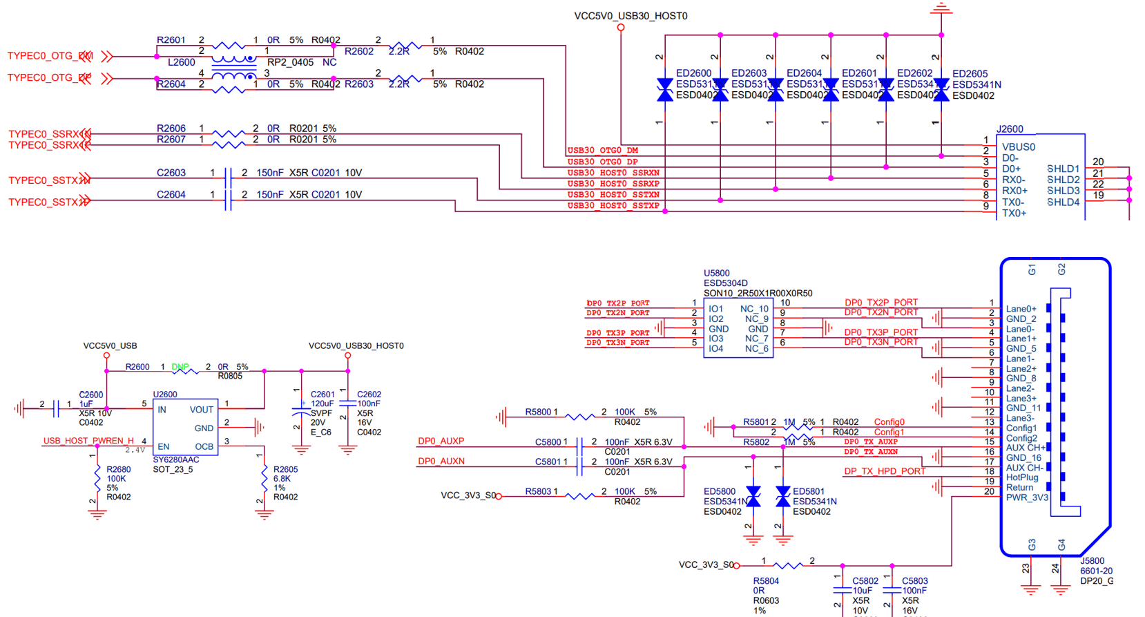
Figure 21 RK3588 Type-A USB3.1/DP Interface
4.3.5 Type-C to Type-A USB 2.0/DP Hardware Circuit
This solution applies to RK3588 Type-C0 and Type-C1, and can be split into independent Type-A USB 2.0 and DP (4 x Lane) interfaces.
Taking the RK3588 NVR Demo Board Type-C1 to Type-A USB 2.0/DP hardware circuit design as an example:
- All 4 lanes of TYPEC1 USBDP PHY are used for the DP interface, and USB does not use USBDP PHY.
- When TYPEC1 USB is only used in HOST mode, TYPEC1_USB20_OTG_ID and TYPEC1_USB20_VBUSDET can be left floating.
- The power supply for Type-A VBUS (VCC5V0_USB20_HOST) is controlled by GPIO. When OTG is in HOST mode, VBUS output is on. In addition, the output current of the voltage regulator chip SY6280AAC is determined by the resistor connected to the OCB pin: Ilim(A)=6800/Rset(ohm). As shown in Figure 23, VBUS output current limit is 1.45A.
- For the corresponding DTS configuration of Type-C to Type-A USB 2.0/DP, refer to the Type-C to Type-A USB 2.0/DP DTS configuration.
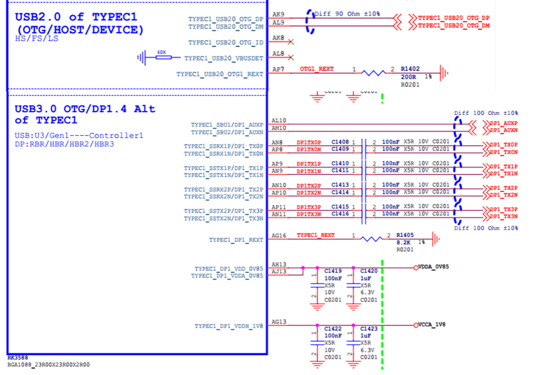
Figure 22 RK3588 Type-A USB 2.0/DP Circuit
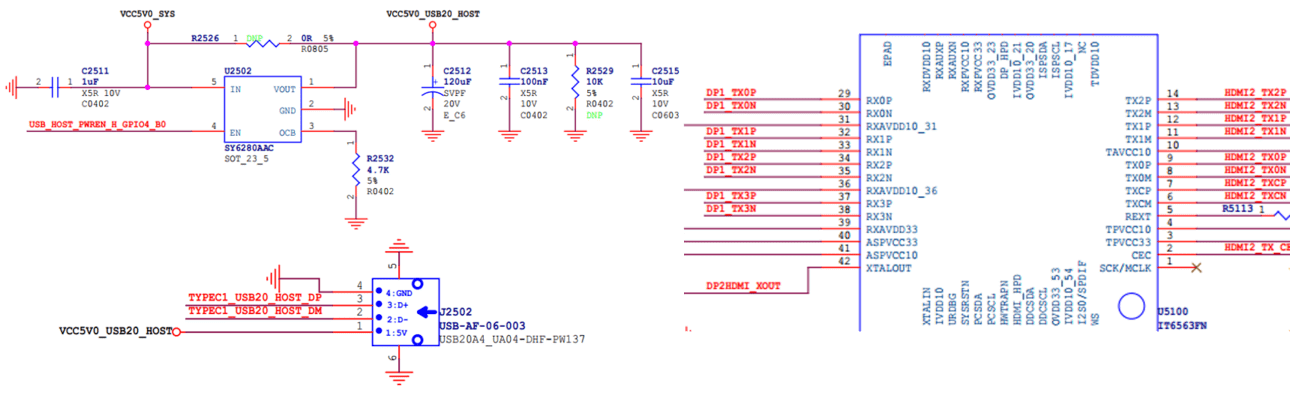
Figure 23 RK3588 Type-A USB2/DP to HDMI Interface
4.3.6 Type-A USB 3.1 Hardware Circuit
This solution applies to RK3588 Type-C0, Type-C1, and USB 3.1 HOST2. For Type-C0/C1, refer to the USB 3.1 part of the Type-A USB 3.1/DP hardware circuit design.
This section focuses on the Type-A USB 3.1 hardware circuit design for USB 3.1 HOST2.
As mentioned in the previous section "RK3588 USB Controller and PHY Overview", USB 3.1 HOST_2 (USB30_2) controller does not have a USB 2.0 PHY, so USB 3.1 HOST_2 needs to be combined with USB 2.0 HOST0/1 to form a complete USB 3.1 interface.
Taking the RK3588 EVB2 USB30_2 HOST hardware circuit design as an example:
- USB 3.1 HOST2 and USB 2.0 HOST1 form a complete USB 3.1 interface.
- According to the chip design of RK3588, USB 3.1 HOST2 can also be combined with Type-C0/1 USB 2.0, but considering that TypeC0/C1 may also be used as USB Device, and the Device and Host functions of the USB 3.1 OTG controller cannot be used simultaneously [2], it is recommended to combine USB 3.1 HOST2 only with USB 2.0 HOST0/1 to simplify hardware and software design.
- For the corresponding DTS configuration of Type-A USB 3.1, refer to the Type-A USB 3.1 DTS configuration.
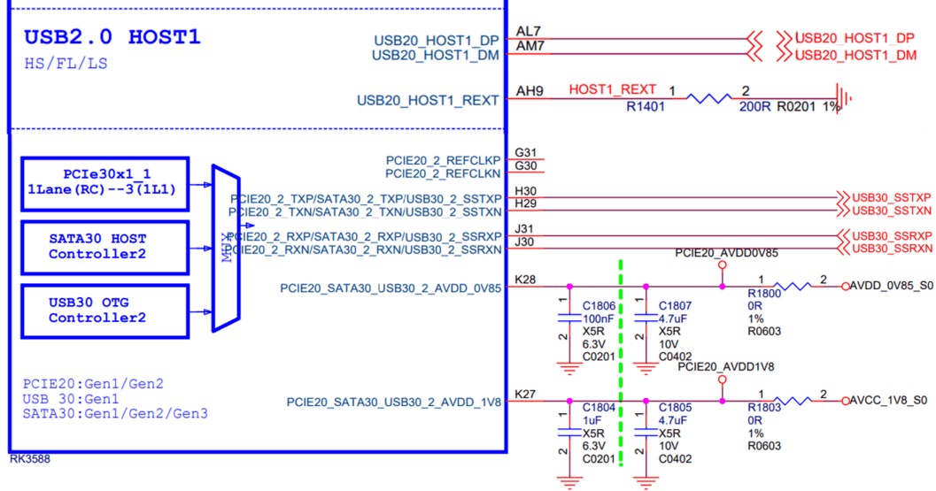
Figure 24 RK3588 USB 3.1 HOST2 Circuit
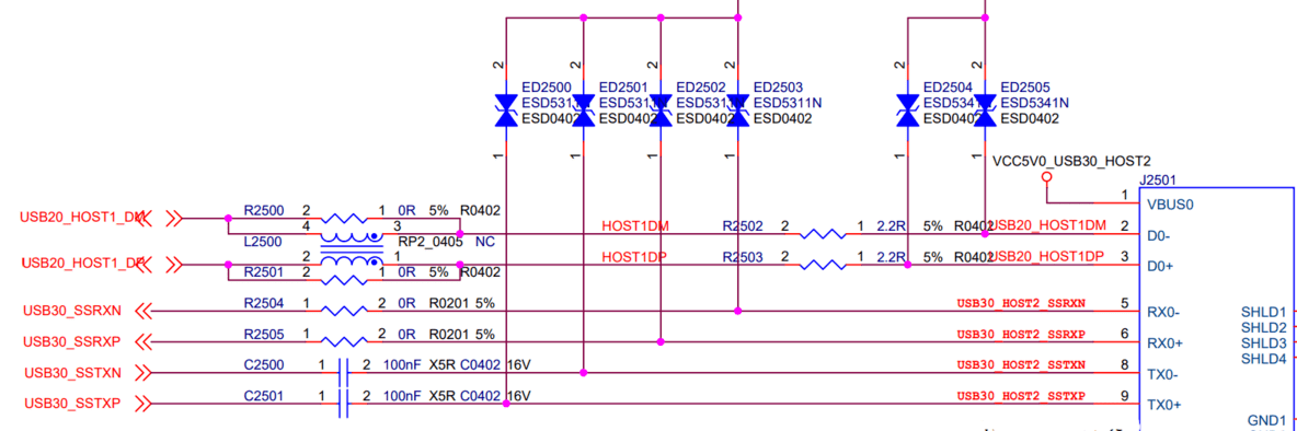
Figure 25 RK3588 USB 3.1 HOST2 Interface
4.3.7 Type-A USB 2.0 Hardware Circuit
This solution applies to RK3588 USB 2.0 HOST0/1.
Taking the RK3588 EVB1 USB 2.0 HOST0/1 hardware circuit design as an example:
- USB 2.0 HOST0/1 share the VBUS power supply (VCC5V0_USB20_HOST), which is controlled by GPIO to enable the voltage regulator chip SY6280AAC to output VBUS. The maximum output current is determined by the resistor connected to the OCB pin of the voltage regulator chip: Ilim(A)=6800/Rset(ohm). As shown in Figure 26, the VBUS output current limit is 1.45A.
- For the corresponding DTS configuration of Type-A USB 2.0, refer to the Type-A USB 2.0 DTS configuration.
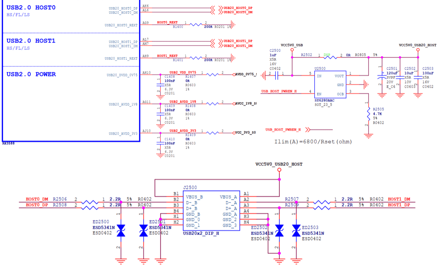
Figure 26 RK3588 USB 2.0 HOST0/1 Circuit
5. RK3588 USB DTS Configuration
RK3588 USB DTS configuration includes: chip-level USB controller / PHY DTSI configuration and board-level DTS configuration.
For detailed configuration methods, refer to the kernel documentation:
- kernel/Documentation/devicetree/bindings/usb/snps,dwc3.yaml
- kernel/Documentation/devicetree/bindings/usb/generic-ohci.yaml
- kernel/Documentation/devicetree/bindings/usb/generic-ehci.yaml
- kernel/Documentation/devicetree/bindings/connector/usb-connector.yaml
- kernel/Documentation/devicetree/bindings/phy/phy-rockchip-inno-usb2.yaml
- kernel/Documentation/devicetree/bindings/phy/phy-rockchip-usbdp.yaml
- kernel/Documentation/devicetree/bindings/phy/phy/phy-rockchip-naneng-combphy.txt
5.1 USB Chip-Level DTSI Configuration
The main nodes related to USB controllers and PHYs in the RK3588 DTSI file are as follows. Since the USB DTSI node configures the common resources and properties of the USB controller and PHY, developers are advised not to modify them.
The DTSI configuration for USB 3.1 OTG0, USB 2.0 HOST0/1, and USB 3.1 HOST2 is in rk3588s-evb.dtsi.
The DTSI configuration for USB 3.1 OTG1 is in rk3588-evb.dts.
The complete DTSI paths are as follows:
arch/arm64/boot/dts/rockchip/rk3588s.dtsi
arch/arm64/boot/dts/rockchip/rk3588.dtsi
Note:
All USB controllers and PHYs of RK3588/RK3588S are configured as status = "okay" in rk3588s-evb.dtsi and rk3588-evb.dtsi. If the board-level DTS file includes these two EVB DTSI files, you only need to set the unused USB nodes to "disabled" in the board-level DTS file.
The correspondence between USB interfaces and USB DTS nodes is shown in Table 16.
| USB Interface Name (Schematic) | USB Controller DTS Node | USB PHY DTS Node |
|---|---|---|
| TYPEC0 | usbdrd3_0 | u2phy0_otg |
| TYPEC0 | usbdrd_dwc3_0 | usbdp_phy0 |
| TYPEC0 | usbdrd_dwc3_0 | usbdp_phy0_u3 |
| TYPEC1 | usbdrd3_1 | u2phy1_otg |
| TYPEC1 | usbdrd_dwc3_1 | usbdp_phy1 |
| TYPEC1 | usbdrd_dwc3_1 | usbdp_phy1_u3 |
| USB20_HOST0 | usb_host0_ehci | u2phy2 |
| USB20_HOST0 | usb_host0_ohci | u2phy2_host |
| USB20_HOST1 | usb_host1_ehci | u2phy3 |
| USB20_HOST1 | usb_host1_ohci | u2phy3_host |
| USB30_2 | usbhost3_0 | combphy2_psu |
| USB30_2 | usbhost_dwc3_0 |
USB controller DTSI nodes are as follows:
# USB3.1 OTG0 Controller
usbdrd3_0: usbdrd3_0 {
    compatible = "rockchip,rk3588-dwc3", "rockchip,rk3399-dwc3";
    usbdrd_dwc3_0: usb@fc000000 {
        compatible = "snps,dwc3";
    };
};

# USB2.0 HOST0 Controller
usb_host0_ehci: usb@fc800000 {
    compatible = "generic-ehci";
};
usb_host0_ohci: usb@fc840000 {
    compatible = "generic-ohci";
};

# USB2.0 HOST1 Controller
usb_host1_ehci: usb@fc880000 {
    compatible = "generic-ehci";
};
usb_host1_ohci: usb@fc8c0000 {
    compatible = "generic-ohci";
};

# USB3.1 HOST2 Controller
usbhost3_0: usbhost3_0 {
    compatible = "rockchip,rk3588-dwc3", "rockchip,rk3399-dwc3";
    usbhost_dwc3_0: usb@fcd00000 {
        compatible = "snps,dwc3";
    };
};

# USB3.1 OTG1 Controller
usbdrd3_1: usbdrd3_1 {
    compatible = "rockchip,rk3588-dwc3", "rockchip,rk3399-dwc3";
    usbdrd_dwc3_1: usb@fc400000 {
        compatible = "snps,dwc3";
    };
};
USB PHY DTSI nodes are as follows:
Note: USB PHY and USB controller have a one-to-one correspondence and must be configured in pairs. For the internal connection between USB PHY and controller, refer to Figure 1 and Table 16 in the RK3588 USB Controller and PHY Overview. In the DTSI node, the "phys" property of the USB controller node associates the corresponding USB PHY.
# USB2.0 PHY0
usb2phy0_grf: syscon@fd5d0000 {
    compatible = "rockchip,rk3588-usb2phy-grf", "syscon", "simple-mfd";
    u2phy0: usb2-phy@0 {
        compatible = "rockchip,rk3588-usb2phy";
        u2phy0_otg: otg-port {
            #phy-cells = <0>;
            status = "disabled";
        };
    };
};

# USB2.0 PHY1
usb2phy1_grf: syscon@fd5d4000 {
    # ... (other configuration)
};

# USB2.0 PHY2
usb2phy2_grf: syscon@fd5d8000 {
    # ... (other configuration)
};

# USB2.0 PHY3
usb2phy3_grf: syscon@fd5dc000 {
    # ... (other configuration)
};

# USB3.1/DP Combo PHY0
usbdp_phy0: phy@fed80000 {
    compatible = "rockchip,rk3588-usbdp-phy";
    usbdp_phy0_dp: dp-port {
        #phy-cells = <0>;
        status = "disabled";
    };
    usbdp_phy0_u3: u3-port {
        #phy-cells = <0>;
        status = "disabled";
    };
};

# USB3.1/DP Combo PHY1
usbdp_phy1: phy@fed90000 {
    # ... (other configuration)
};

# USB3.1/SATA/PCIe PHY2
combphy2_psu: phy@fee20000 {
    compatible = "rockchip,rk3588-naneng-combphy";
    # ... (other configuration)
};
5.2 Type-C USB 3.1/DP Full-Function DTS Configuration
Refer to the DTS configuration of Type-C0 interface in arch/arm64/boot/dts/rockchip/rk3588-evb1-lp4.dtsi.
# The "rockchip,typec-vbus-det" property of USB2.0 PHY indicates support for Type-C VBUS_DET always-high hardware design
&u2phy0_otg {
    rockchip,typec-vbus-det;
};

# USB3.1/DP PHY0, configure "sbu1-dc-gpios" and "sbu2-dc-gpios" properties according to hardware design
&usbdp_phy0 {
    orientation-switch;
    svid = <0xff01>;
    sbu1-dc-gpios = <&gpio4 RK_PA6 GPIO_ACTIVE_HIGH>;
    sbu2-dc-gpios = <&gpio4 RK_PA7 GPIO_ACTIVE_HIGH>;
    port {
        #address-cells = <1>;
        #size-cells = <0>;
        usbdp_phy0_orientation_switch: endpoint@0 {
            reg = <0>;
            remote-endpoint = <&usbc0_orien_sw>;
        };
        usbdp_phy0_dp_altmode_mux: endpoint@1 {
            reg = <1>;
            remote-endpoint = <&dp_altmode_mux>;
        };
    };
};

# USB3.1 OTG0 Controller
&usbdrd_dwc3_0 {
    dr_mode = "otg";
    usb-role-switch;
    port {
        #address-cells = <1>;
        #size-cells = <0>;
        dwc3_0_role_switch: endpoint@0 {
            reg = <0>;
            remote-endpoint = <&usbc0_role_sw>;
        };
    };
};

# VBUS GPIO configuration, controlled by the Type-C controller chip driver
vbus5v0_typec: vbus5v0-typec {
    compatible = "regulator-fixed";
    regulator-name = "vbus5v0_typec";
    regulator-min-microvolt = <5000000>;
    regulator-max-microvolt = <5000000>;
    enable-active-high;
    gpio = <&gpio4 RK_PD0 GPIO_ACTIVE_HIGH>;
    vin-supply = <&vcc5v0_usb>;
    pinctrl-names = "default";
    pinctrl-0 = <&typec5v_pwren>;
};

# Configure external Type-C controller chip FUSB302
# Configure "I2C/interrupts/vbus-supply/usb_con" properties according to actual hardware design
&i2c2 {
    status = "okay";
    usbc0: fusb302@22 {
        compatible = "fcs,fusb302";
        reg = <0x22>;
        interrupt-parent = <&gpio3>;
        interrupts = <RK_PB4 IRQ_TYPE_LEVEL_LOW>;
        pinctrl-names = "default";
        pinctrl-0 = <&usbc0_int>;
        vbus-supply = <&vbus5v0_typec>;
        status = "okay";
        ports {
            #address-cells = <1>;
            #size-cells = <0>;
            port@0 {
                reg = <0>;
                usbc0_role_sw: endpoint@0 {
                    remote-endpoint = <&dwc3_0_role_switch>;
                };
            };
        };
    };
    usb_con: connector {
        compatible = "usb-c-connector";
        label = "USB-C";
        data-role = "dual";
        power-role = "dual";
        try-power-role = "sink";
        op-sink-microwatt = <1000000>;
        sink-pdos = <PDO_FIXED(5000, 1000, PDO_FIXED_USB_COMM)>;
        source-pdos = <PDO_FIXED(5000, 3000, PDO_FIXED_USB_COMM)>;
        altmodes {
            #address-cells = <1>;
            #size-cells = <0>;
            altmode@0 {
                reg = <0>;
                svid = <0xff01>;
                vdo = <0xffffffff>;
            };
        };
        ports {
            # ... (other configuration)
        };
    };
};
Note:
If you use the HUSB311 chip to replace the FUSB302 chip, you only need to make simple modifications based on the FUSB302 DTS configuration. Refer to the following modification:
# Configure external Type-C controller chip HUSB311
&i2c2 {
    usbc0: husb311@4e {
        compatible = "hynetek,husb311";
        reg = <0x4e>;
        # ... (other configuration)
    };
};
5.3 Type-C to Type-A USB 3.1/DP DTS Configuration
Refer to the DTS configuration of Type-C0 to Type-A USB 3.1/DP in arch/arm64/boot/dts/rockchip/rk3588-evb2-lp4.dtsi.
# USB2.0 PHY0 configures the "phy-supply" property to control VBUS output 5V

# Note: Using phy-supply cannot achieve dynamic VBUS switching. If OTG exclusively occupies the GPIO, does not share with other HOSTs, and OTG needs to support Device/HOST, it should be configured as "vbus-supply = <&vcc5v0_otg>" to achieve dynamic VBUS switching.
&u2phy0_otg {
    phy-supply = <&vcc5v0_host>;
};

# VBUS GPIO configuration, this GPIO is controlled in the USB2.0 PHY driver
vcc5v0_host: vcc5v0-host {
    compatible = "regulator-fixed";
    regulator-name = "vcc5v0_host";
    regulator-boot-on;
    regulator-always-on;
    regulator-min-microvolt = <5000000>;
    regulator-max-microvolt = <5000000>;
    enable-active-high;
    gpio = <&gpio4 RK_PA1 GPIO_ACTIVE_HIGH>;
    vin-supply = <&vcc5v0_usb>;
    pinctrl-names = "default";
};
pinctrl-0 = <&vcc5v0_host_en>;

# USB3.1/DP PHY0, only need to configure DP to use lane2/3, the driver will automatically assign lane0/1 to USB3.1 Rx/Tx

# If the hardware design uses lane0/1 for DP, configure "rockchip,dp-lane-mux = <0 1>" here

# Note: Even if DP is not supported in the actual circuit, "rockchip,dp-lane-mux" must be configured, otherwise the USBDP PHY driver cannot automatically assign lanes to USB3.1
&usbdp_phy0 {
    rockchip,dp-lane-mux = <2 3>;
};

# USB3.1 OTG0 Controller

# Configure "dr_mode" as "otg", and configure the "extcon" property at the same time to support software switching between Device/Host mode
&usbdrd_dwc3_0 {
    dr_mode = "otg";
    extcon = <&u2phy0>;
    status = "okay";
};
5.4 Type-C to Type-A USB 2.0/DP DTS Configuration
Refer to the DTS configuration of Type-C1 to Type-A USB 2.0/DP in arch/arm64/boot/dts/rockchip/rk3588-nvr-demo.dtsi.
# USB2.0 PHY1 configures the "phy-supply" property to control VBUS output 5V
&u2phy1_otg {
    phy-supply = <&vcc5v0_host>;
};
status = "okay";

# VBUS GPIO configuration, this GPIO is controlled in the USB2.0 PHY driver
vcc5v0_host: vcc5v0-host-regulator {
    compatible = "regulator-fixed";
    regulator-name = "vcc5v0_host";
    regulator-boot-on;
    regulator-always-on;
    regulator-min-microvolt = <5000000>;
    regulator-max-microvolt = <5000000>;
    enable-active-high;
    gpio = <&gpio4 RK_PB0 GPIO_ACTIVE_HIGH>;
    vin-supply = <&vcc5v0_sys>;
    pinctrl-names = "default";
};
pinctrl-0 = <&vcc5v0_host_en>;

# USB3.1/DP PHY1, configure DP to use lane0/1/2/3

# Configure the property "rockchip,dp-lane-mux" according to the actual hardware design

# Configure the property "maximum-speed" to notify the USBDP driver to limit USB to USB2.0 only
&usbdp_phy1 {
    maximum-speed = "high-speed";
};
rockchip,dp-lane-mux = <0 1 2 3>;
status = "okay";

&usbdp_phy1_dp {
    status = "okay";
};

&usbdp_phy1_u3 {
    status = "okay";
};

# Configure the property "maximum-speed" to notify the DWC3 driver to limit USB to USB2.0 only
&usbdrd_dwc3_1 {
    dr_mode = "host";
    maximum-speed = "high-speed";
    status = "okay";
};
snps,dis_u2_susphy_quirk;
snps,usb2-lpm-disable;
5.5 Type-C USB 2.0 only DTS Configuration
Configuration 1. Hardware circuit with external Type-C controller chip, supports PD
Refer to the DTS configuration of Type-C0 USB 2.0 OTG in arch/arm64/boot/dts/rockchip/rk3588s-tablet-rk806-single.dtsi
# USB2.0 PHY0 registers typec orientation switch, used to interact with the TCPM subsystem to get USB hot-plug information
&u2phy0 {
    orientation-switch;
    status = "okay";
    port {
        #address-cells = <1>;
        #size-cells = <0>;
        u2phy0_orientation_switch: endpoint@0 {
            reg = <0>;
            remote-endpoint = <&usbc0_orien_sw>;
        };
    };
};

# USB2.0 PHY0 OTG configuration

# Configure the property "rockchip,sel-pipe-phystatus" to select GRF to control pipe phystatus, replacing USBDP PHY control

# Configure the property "rockchip,typec-vbus-det" to indicate support for Type-C VBUS_DET always high hardware design

# Configure the property "rockchip,dis-u2-susphy" to disable the USB2 PHY driver from dynamically entering suspend mode
&u2phy0_otg {
    rockchip,sel-pipe-phystatus;
    rockchip,typec-vbus-det;
    rockchip,dis-u2-susphy;
    status = "okay";
};

# Disable all related nodes of USBDP PHY0 to keep USBDP PHY0 uninitialized for lowest power consumption
&usbdp_phy0 {
    status = "disabled";
};
&usbdp_phy0_dp {
    status = "disabled";
};
&usbdp_phy0_u3 {
    status = "disabled";
};

# Configure USB3.1 OTG0 Controller

# Configure "phys = <&u2phy0_otg>", i.e., do not reference USBDP PHY

# Configure maximum-speed = "high-speed" to notify the DWC3 driver to limit USB to USB2.0 only

# Configure "snps,dis_u2_susphy_quirk" to disable the controller hardware from suspending usb2 phy, improving USB communication stability

# Configure "snps,usb2-lpm-disable" to disable LPM in Host mode, improving USB device compatibility
&usbdrd_dwc3_0 {
    dr_mode = "otg";
    status = "okay";
    maximum-speed = "high-speed";
    phys = <&u2phy0_otg>;
    phy-names = "usb2-phy";
    usb-role-switch;
    snps,dis_u2_susphy_quirk;
    snps,usb2-lpm-disable;
    port {
        #address-cells = <1>;
        #size-cells = <0>;
        dwc3_0_role_switch: endpoint@0 {
            reg = <0>;
            remote-endpoint = <&usbc0_role_sw>;
        };
    };
};

# Configure external Type-C controller chip FUSB302
# Configure the properties "I2C/interrupts/vbus-supply/usb_con" according to the actual hardware design
# Configure the property remote-endpoint = <&u2phy0_orientation_switch> for usbc0_orien_sw
&i2c8 {
    status = "okay";
    pinctrl-names = "default";
    pinctrl-0 = <&i2c8m2_xfer>;
    usbc0: fusb302@22 {
        compatible = "fcs,fusb302";
        reg = <0x22>;
        interrupt-parent = <&gpio0>;
        interrupts = <RK_PC4 IRQ_TYPE_LEVEL_LOW>;
        pinctrl-names = "default";
        pinctrl-0 = <&usbc0_int>;
        vbus-supply = <&vbus5v0_typec>;
        status = "okay";
        ports {
            #address-cells = <1>;
            #size-cells = <0>;
            port@0 {
                reg = <0>;
                usbc0_role_sw: endpoint@0 {
                    remote-endpoint = <&dwc3_0_role_switch>;
                };
            };
        };
    };
    usb_con: connector {
        compatible = "usb-c-connector";
        label = "USB-C";
        data-role = "dual";
        power-role = "dual";
        # ... (other configurations)
        ports {
            #address-cells = <1>;
            #size-cells = <0>;
            port@0 {
                reg = <0>;
                usbc0_orien_sw: endpoint {
                    remote-endpoint = <&u2phy0_orientation_switch>;
                };
            };
        };
    };
};
Configuration 2. Hardware circuit without external Type-C controller chip, supports Device only
Refer to the DTS configuration of Type-C0 USB 2.0 Device in arch/arm64/boot/dts/rockchip/rk3588-evb5-lp4.dtsi
# USB2.0 PHY0 OTG configuration
# Configure the property "rockchip,sel-pipe-phystatus" to select GRF to control pipe phystatus, replacing USBDP PHY control
# Configure the property "rockchip,dis-u2-susphy" to disable the USB2 PHY driver from dynamically entering suspend mode
&u2phy0_otg {
    rockchip,sel-pipe-phystatus;
    rockchip,dis-u2-susphy;
    status = "okay";
};

# Disable all related nodes of USBDP PHY0 to keep USBDP PHY0 uninitialized for lowest power consumption
&usbdp_phy0 {
    status = "disabled";
};
&usbdp_phy0_dp {
    status = "disabled";
};
&usbdp_phy0_u3 {
    status = "disabled";
};

# Configure USB3.1 OTG0 Controller
# Configure dr_mode = "peripheral" to notify the DWC3 driver to initialize as Device only mode
# Configure "phys = <&u2phy0_otg>", i.e., do not reference USBDP PHY
# Configure maximum-speed = "high-speed" to notify the DWC3 driver to limit USB to USB2.0 only
# Configure "snps,dis_u2_susphy_quirk" to disable the controller hardware from suspending usb2 phy, improving USB communication stability
&usbdrd_dwc3_0 {
    dr_mode = "peripheral";
    phys = <&u2phy0_otg>;
    phy-names = "usb2-phy";
    maximum-speed = "high-speed";
    snps,dis_u2_susphy_quirk;
};
Configuration 3. Hardware circuit without external Type-C controller chip, supports OTG (requires additional CC to ID level conversion circuit)
# USB2.0 PHY0 OTG configuration
# Configure the property "rockchip,sel-pipe-phystatus" to select GRF to control pipe phystatus, replacing USBDP PHY control
# Configure the property "rockchip,dis-u2-susphy" to disable the USB2 PHY driver from dynamically entering suspend mode
&u2phy0_otg {
    rockchip,sel-pipe-phystatus;
    rockchip,dis-u2-susphy;
    status = "okay";
};

# Disable all related nodes of USBDP PHY0 to keep USBDP PHY0 uninitialized for lowest power consumption
&usbdp_phy0 {
    status = "disabled";
};
&usbdp_phy0_dp {
    status = "disabled";
};
&usbdp_phy0_u3 {
    status = "disabled";
}

# Configure USB3.1 OTG0 Controller
# Configure dr_mode = "otg"
# Configure "phys = <&u2phy0_otg>", i.e., do not reference USBDP PHY
# Configure maximum-speed = "high-speed" to notify the DWC3 driver to limit USB to USB2.0 only
# Configure the "extcon" property to support automatic switching between Device/Host mode
# Configure "snps,dis_u2_susphy_quirk" to disable the controller hardware from suspending usb2 phy, improving USB communication stability
# Configure "snps,usb2-lpm-disable" to disable LPM in Host mode, improving USB device compatibility
&usbdrd_dwc3_0 {
    dr_mode = "otg";
    phys = <&u2phy0_otg>;
    phy-names = "usb2-phy";
    maximum-speed = "high-speed";
    extcon = <&u2phy0>;
    snps,dis_u2_susphy_quirk;
    snps,usb2-lpm-disable;
};
5.6 Type-A USB 3.1 DTS Configuration
Refer to the DTS configuration of USB30_2 HOST in arch/arm64/boot/dts/rockchip/rk3588-evb2-lp4.dtsi
# USB2.0 PHY3 configures the "phy-supply" property to control VBUS output 5V
&u2phy3_host {
    phy-supply = <&vcc5v0_host>;
}

# VBUS GPIO configuration, this GPIO is controlled in the USB2.0 PHY driver
vcc5v0_host: vcc5v0-host {
    compatible = "regulator-fixed";
    regulator-name = "vcc5v0_host";
    regulator-boot-on;
    regulator-always-on;
    regulator-min-microvolt = <5000000>;
    regulator-max-microvolt = <5000000>;
    enable-active-high;
    gpio = <&gpio4 RK_PA1 GPIO_ACTIVE_HIGH>;
    vin-supply = <&vcc5v0_usb>;
    pinctrl-names = "default";
    pinctrl-0 = <&vcc5v0_host_en>;
};

# Enable USB3.1/SATA/PCIe Combo PHY
&combphy2_psu {
    status = "okay";
};

# Configure USB3.1 HOST2 Controller
&usbhost3_0 {
    status = "okay";
};
&usbhost_dwc3_0 {
    dr_mode = "host";
    status = "okay";
};
5.7 Type-A USB 2.0 DTS Configuration
Refer to the DTS configuration of USB 2.0 HOST0/1 in arch/arm64/boot/dts/rockchip/rk3588-evb1-lp4.dtsi.
# USB2.0 PHY2/3 configures the "phy-supply" property to control VBUS output 5V
&u2phy2_host {
    phy-supply = <&vcc5v0_host>;
};
&u2phy3_host {
    phy-supply = <&vcc5v0_host>;
};

# VBUS GPIO configuration, this GPIO is controlled in the USB2.0 PHY driver
vcc5v0_host: vcc5v0-host {
    compatible = "regulator-fixed";
    regulator-name = "vcc5v0_host";
    regulator-boot-on;
    regulator-always-on;
    regulator-min-microvolt = <5000000>;
    regulator-max-microvolt = <5000000>;
    enable-active-high;
    gpio = <&gpio4 RK_PB0 GPIO_ACTIVE_HIGH>;
    vin-supply = <&vcc5v0_usb>;
    pinctrl-names = "default";
    pinctrl-0 = <&vcc5v0_host_en>;
};

# USB2.0 HOST0/1 Controller
&usb_host0_ehci {
    status = "okay";
};
&usb_host0_ohci {
    status = "okay";
};
&usb_host1_ehci {
    status = "okay";
};
&usb_host1_ohci {
    status = "okay";
};
5.8 Micro USB DTS Configuration
RK3588 OTG can support Micro USB 2.0 interface design, using the file arch/arm64/boot/dts/rockchip/rk3588-evb1-lp4.dtsi as an example.
The following nodes and properties need to be deleted in the DT configuration:
- usbc0 node and its subnodes;
- orientation-switch property and port subnode in the usbdp_phy0 node;
- usb-role-switch property and port subnode in the usbdrd_dwc3_0 node;
- rockchip,typec-vbus-det property in the u2phy0_otg node;
- usb-typec subnode in the pinctrl node.
The following nodes and properties need to be added in the DT configuration:
vcc5v0_otgnode for controlling vbus supply;- Add
vbus-supplyproperty to theu2phy0_otgnode; - Add
extcon = <&u2phy0>; property to theusbdrd_dwc3_0node.
[...] # VBUS GPIO configuration, this GPIO is controlled in the USB2.0 PHY driver
vcc5v0_otg: vcc5v0-otg {
    compatible = "regulator-fixed";
    regulator-name = "vcc5v0_otg";
    regulator-min-microvolt = <5000000>;
    regulator-max-microvolt = <5000000>;
    enable-active-high;
    gpio = <&gpio4 RK_PA7 GPIO_ACTIVE_HIGH>;
    vin-supply = <&vcc5v0_sys>;
    pinctrl-names = "default";
    pinctrl-0 = <&vcc5v0_otg_en>;
};

&pinctrl {

    usb {

        [...]

        vcc5v0_otg_en: vcc5v0-otg-en {
            rockchip,pins = <4 RK_PA7 RK_FUNC_GPIO &pcfg_pull_up>;
        };

        [...]

    };

    [...]

};

# Configure status according to actual design. If both USB3 and DP are not used, it is recommended to disable all related nodes of USBDP PHY0 to reduce power consumption
&usbdp_phy0 {
    maximum-speed = "high-speed";
    status = "okay";
};

&usbdp_phy0_dp {
    status = "okay";
};

&usbdp_phy0_u3 {
    status = "okay";
};

&u2phy0 {
    status = "okay";
};

&u2phy0_otg {
    vbus-supply = <&vcc5v0_otg>;
    rockchip,sel-pipe-phystatus;
    rockchip,dis-u2-susphy;
    status = "okay";
};

&usbdrd_dwc3_0 {
    status = "okay";
    dr_mode = "otg";
    maximum-speed = "high-speed";
    extcon = <&u2phy0>;
    snps,dis_u2_susphy_quirk;
    snps,usb2-lpm-disable;
};
5.9 Notes on Linux USB DT Configuration
5.9.1 Important USB DT Property Descriptions
5.9.1.1 USB Controller
- "usb-role-switch" is only used for standard Type-C interfaces (with PD controller chip), and must be configured with
dr_mode = "otg"; ifdr_modeis not "otg", do not configure "usb-role-switch"; - One of the main functions of the "extcon" property is to dynamically switch OTG mode, suitable for hardware circuit designs with non-standard Type-C interfaces (with PD controller chip), such as: USB Micro interface or Type-A interface, and in schemes where the controller is configured as "otg" mode, to achieve dynamic OTG mode switching;
- "snps,dis_u2_susphy_quirk" disables the USB controller hardware from automatically suspending usb2 phy, mainly used for USB 2.0 only schemes to improve USB communication stability;
- "snps,usb2-lpm-disable" disables the LPM function in USB controller Host mode, mainly used for USB 2.0 only schemes to improve USB device compatibility.
5.9.1.2 USB2 PHY
- Both "vbus-supply" and "phy-supply" are used to control VBUS output 5V, but there are differences in usage. "vbus-supply" is used for OTG ports and supports dynamic VBUS switching. "phy-supply" is used for USB2 HOST ports, VBUS 5V is always on after system power-on;
- "rockchip,sel-pipe-phystatus" is used to configure the GRF USB control register, selecting GRF to control pipe phystatus, replacing USBDP PHY control. Mainly used for USB 2.0 only schemes. If USBDP PHY is not enabled, this property must be added, otherwise the USB device cannot work properly;
- "rockchip,typec-vbus-det" is used to support hardware designs with Type-C VBUS_DET always high;
- "rockchip,dis-u2-susphy" disables the USB2 PHY driver from dynamically entering suspend mode, mainly used for USB 2.0 only schemes, keeping the USB2 PHY output clock to the USB controller.
5.9.1.3 USBDP Combo PHY
- "rockchip,dp-lane-mux", in non-full-featured Type-C schemes, configures the Lane number mapped by DP. DP supports 2 or 4 lanes, for example,
"rockchip,dp-lane-mux = <2, 3>;"means DP Lane0 maps to USBDP PHY Lane2, DP Lane1 maps to USBDP PHY Lane3; similarly,"rockchip,dp-lane-mux = <0, 1, 2, 3>;"means DP Lane0 maps to USBDP PHY Lane0, and so on.
6. RK3588 USB OTG mode switching commands
RK3588 SDK supports forcibly setting USB OTG to Host mode or Peripheral mode by software, regardless of the OTG ID level of the USB hardware circuit or the Type-C interface.
There are two ways to switch the USB OTG controller to Peripheral mode or Host mode in the RK3588 Linux-5.10 kernel. Note: Method 1 depends on the correct configuration of the USB DTS and can only be used for hardware circuit designs with non-Type-C interfaces. Method 2 has no such limitation. Therefore, if you are not sure whether the software and hardware are correctly adapted, it is recommended to use Method 2 first.
Method 1. [Legacy]
- Force host mode
echo host > /sys/devices/platform/fd5d0000.syscon/fd5d0000.syscon:usb2-phy@0/otg_mode - Force peripheral mode
echo peripheral > /sys/devices/platform/fd5d0000.syscon/fd5d0000.syscon:usb2-phy@0/otg_mode
Method 2. [New]
- Force host mode
echo host > /sys/kernel/debug/usb/fc000000.usb/mode - Force peripheral mode
echo device > /sys/kernel/debug/usb/fc000000.usb/mode
7. Type-C Controller Chip Support List
| Type-C Controller | Linux-4.4 | Linux-4.19 | Linux-5.10 | Linux-6.1 | Description |
|---|---|---|---|---|---|
| ANX7411 | Not supported | Not supported | Not supported | Debugging | Linux-6.1 software driver is already supported, functionality needs further debugging |
| AW35615 | Supported | Supported | Supported | Supported | Recommended for priority use, good compatibility with DisplayPort Alt Mode |
| ET7301B | Supported | Supported | Supported | Supported | Software and hardware fully compatible with FUSB302 |
| ET7303 | Not supported | Supported | Supported | Supported | Hardware compatible with FUSB302, software driver is highly similar to RT1711 |
| FUSB302 | Supported | Supported | Supported | Supported | Default chip used by RK3588 EVB, recommended for priority use |
| HUSB311 | Not supported | Supported | Supported | Supported | Hardware compatible with FUSB302, but software driver is not compatible |
| RT1711H | Not supported | Supported | Supported | Supported | Hardware compatible with FUSB302/ET7303, software driver is highly similar to ET7303 |
| WUSB3801 | Not supported | Not supported | Not supported | Not supported | High bit error rate, cannot guarantee communication stability |
- note1. Linux-4.4 does not support the TCPM software framework, so only FUSB302/ET7301B are supported, and both can be directly replaced without modifying software or hardware;
- note2. The small package ET7303 (according to the manufacturer, there is currently no large package) has been verified on the RK platform. The kernel needs to separately enable CONFIG_TYPEC_ET7303. For detailed DTS configuration, please refer to the usbc0 node in the section Type-C USB 3.1/DP Full Function DTS Configuration, just modify the node name, reg address, and compatible property;
- note3. FUSB302 can be directly replaced with HUSB311. The kernel needs to separately use CONFIG_TYPEC_HUSB311, and the DTS configuration notes are the same as note2 above;
- note4. RT1711H hardware is compatible with FUSB302/ET7303, and the software driver is highly similar to ET7303. The kernel needs to separately enable CONFIG_TYPEC_RT1711H, and the DTS configuration notes are the same as note2 above;
8. Reference Documents
- "Universal Serial Bus Type-C Cable and Connector Specification"
- "Rockchip_Developer_Guide_USB_CN"