
K1 M.2 Interface Description
I. M.2 Interface
M.2 is the physical size and pin electrical interface specification for internal expansion cards and related connectors in computers. It adopts a new physical layout and connector to replace the PCI Express (PCIE) and mSATA interface standards. M.2 has flexible physical specifications, allowing for more types of module widths and lengths, and is compatible with more advanced interfaces, making M.2 more suitable for daily applications than mSATA, especially for solid-state drives in devices such as ultrabooks or tablets.
M.2 is developed by the PCI-SIG and SATA-IO standard organizations, and is defined in both the PCI-SIG M.2 and SATA Rev. 3.2 specifications. It was originally called NGFF (Next Generation Form Factor) and was officially renamed M.2 in 2013.
For detailed information, please refer to Wikipedia.
There are four common M.2 interfaces as follows:
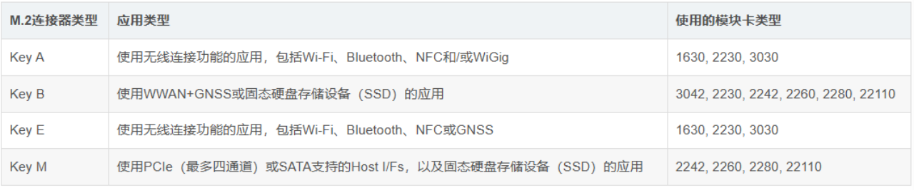 The pin shapes and pin definitions corresponding to different types of interfaces are also different.
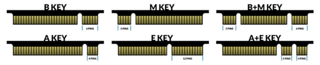 The pin definitions are as follows:
- KEY-A pin definition
- KEY-B pin definition
- KEY-E pin definition
- KEY-M pin definition
M.2 Interface on the K1 Board
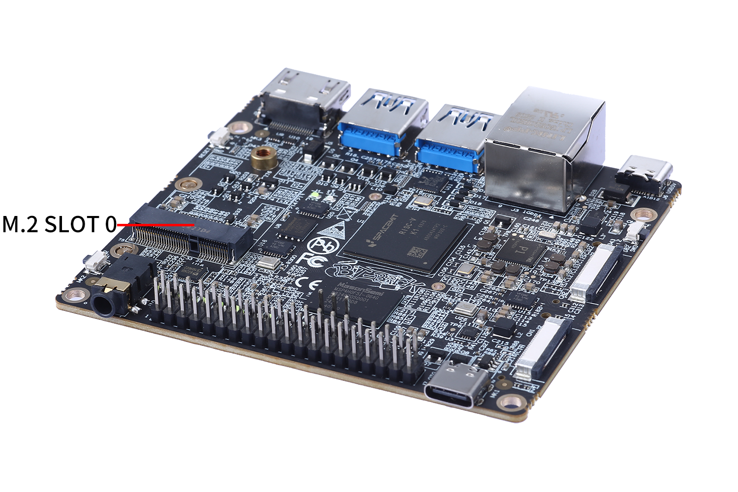
The K1 board integrates three M.2 interfaces, as shown in the following figure:
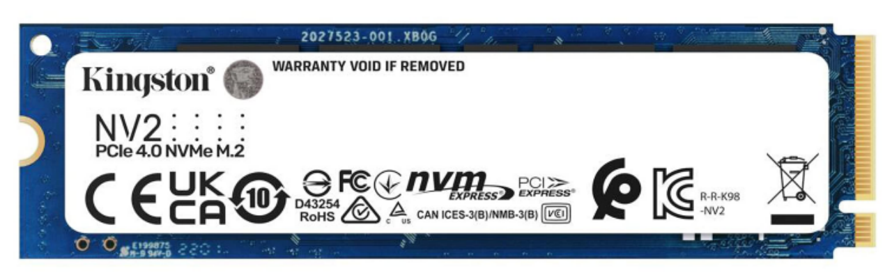
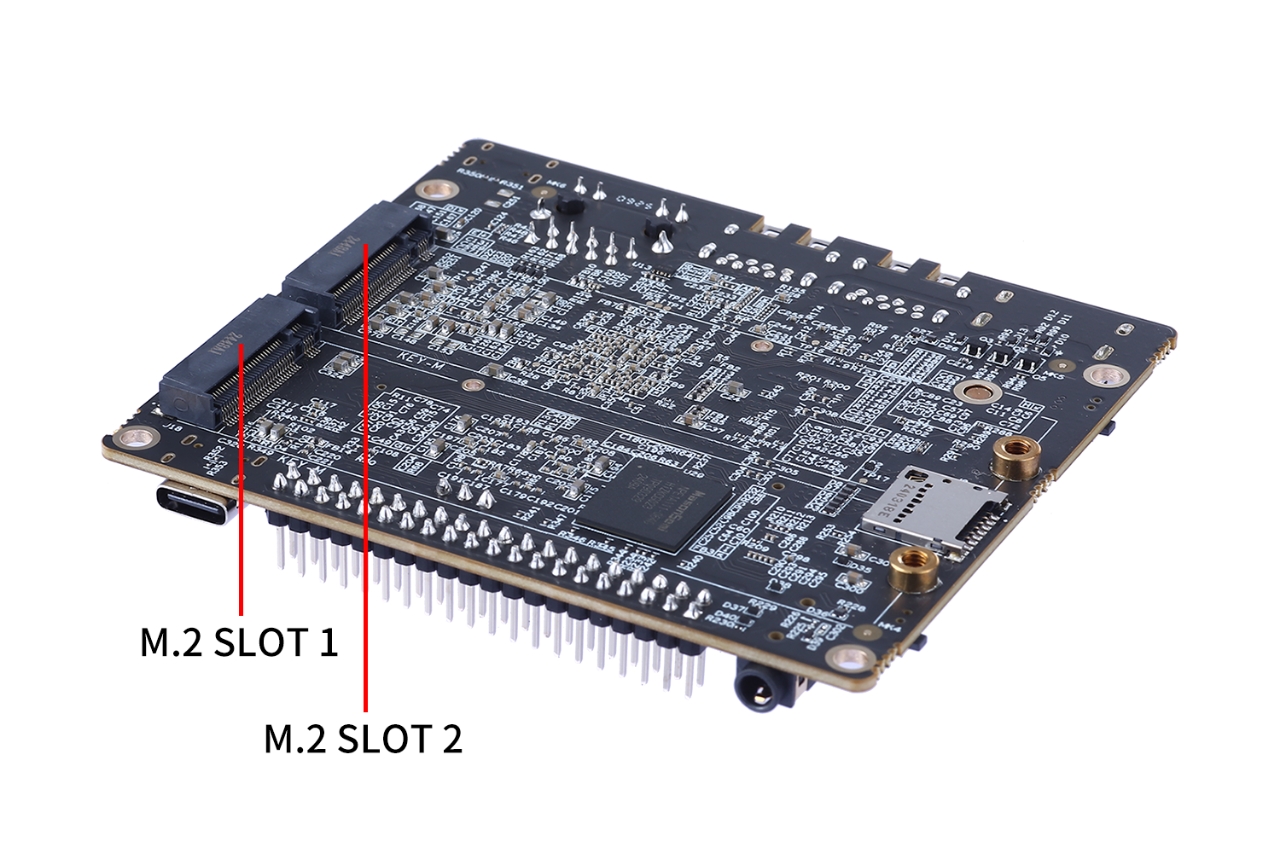 Among them, M.2 SLOT 1 and 2 are standard M.2 KEY-M interface definitions, which can directly support solid-state drives with the NVME interface. The length of the solid-state drive can be 2280.
Users can choose SSDs with the mainstream NVME interface. The installation method is shown in the following figure:
Among them, M.2 SLOT 1 and 2 are standard M.2 KEY-M interface definitions, which can directly support solid-state drives with the NVME interface. The length of the solid-state drive can be 2280.
Users can choose SSDs with the mainstream NVME interface. The installation method is shown in the following figure:
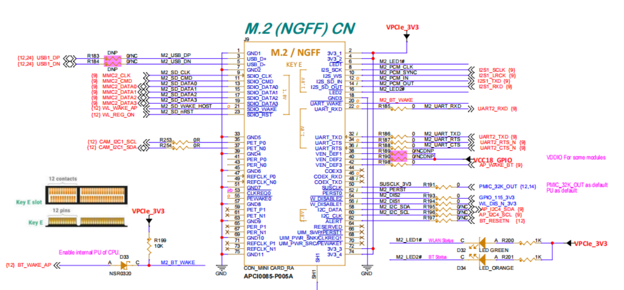
 The other M.2 SLOT 0 is the interface definition of KEY-E, with a length of 2230, which is mainly used to support various wireless modules. Since the processor only has three USB interfaces, the USB interface is not reserved for SLOT 0, and the PCIE interface compatible with NGFF is also removed, so modules with USB and PCIE interface definitions are not supported. The detailed description of the pin definition of the SLOT 0 interface is as follows:
K1 defaults to supporting the hardware modules developed by BIT-BRICK itself, and the supported categories and models are as follows:
| Model | Category | Specification Introduction |
|---|---|---|
| WIFI + Bluetooth | Wireless Module | |
| LORA | Wireless Module | |
| ZIGBEE | Wireless Module | |
| Bluetooth + Star Flash | Wireless Module | |
| GPS | Positioning Module |